Power reception apparatus, vehicle, power transmission apparatus, power transmission and reception system, and control method

a technology for power transmission and reception apparatus, which is applied in the direction of charging stations, electric vehicle charging technology, transportation and packaging, etc., can solve the problems of increasing the number of labor hours in parking the vehicle in the required manner, and achieves the effect of easy alignment with appropriate accuracy, low cost and convenient execution

Active Publication Date: 2017-11-02
HONDA MOTOR CO LTD
View PDF9 Cites 2 Cited by
  • Summary
  • Abstract
  • Description
  • Claims
  • Application Information

AI Technical Summary

Benefits of technology

[0087]According to the invention of (1), (2), and (10) to (16), in aligning the secondary coil with the primary coil, since the relative position and the gradient of the secondary coil relative to the primary coil are displayed in the different display modes on the display unit for the case where the secondary coil is not included in the target zone in relation to the left-right direction, which constitutes the critical aspect in the alignment in the left-right direction and the case where the secondary coil is included in the target zone in relation to the left-right direction, which constitutes the critical aspect in the alignment in the front-rear direction, the operator of the drive part can grasp accurately the relative position of the secondary coil relative to the primary coil in each aspect by watching a screen of the display unit. Consequently, the operator can easily execute the alignment with appropriate accuracy in each aspect by operating the drive part while watching the screen of the display unit. Further, the invention can be realized in a case where a device for measuring a coupling coefficient between the primary coil and the secondary coil or a device for acquiring information on the positions of the primary coil and the secondary coil is provided in addition to the display unit. Thus, the support for the positional alignment is executed at low cost.
[0088]According to the invention of (3), in the aspect where the alignment in the left-right direction is critical, when the information is displayed in the first display mode, the information on the relative position in relation to the left-right direction is displayed more than the information on the relative position in relation to the front-rear direction. Due to this, the operator of the drive part can easily execute the alignment in the left-right direction with appropriate accuracy when he or she watches the screen of the display unit on which the information is displayed in the first display mode.
[0089]According to the invention of (4), in the aspect where the alignment in the front-rear direction is critical, when the information is displayed in the second display mode, the information on the relative position in relation to the front-rear direction is displayed more than the information on the relative position in relation to the left-right direction. Due to this, the operator of the drive part can easily execute the alignment in the front-rear direction with appropriate accuracy when he or she watches the screen of the display unit on which the information is displayed in the second display mode.
[0090]According to the invention of (5), in the first display mode which constitutes the aspect where the alignment in the left-right direction is critical, the gradient of the second coil is displayed on the display unit with higher accuracy. Since the gradient of the secondary coil is dependent mainly on the accuracy with the alignment in the left-right direction, the operator of the drive part can easily execute the alignment in the left-right direction with appropriate accuracy when he or she watches the screen of the display unit on which the information is displayed in the first display mode. On the other hand, when the information is displayed in the second display mode on the display unit, since the gradient of the secondary coil is not displayed with high accuracy, it is considered that the operator who watches the screen in the second display mode tends to concentrate on the alignment in the front-rear direction and hence does nothing about the alignment in the left-right direction operation. As a result, it is possible to restrain the operator of the drive part from changing the relative position in the left-right direction.
[0091]According to the invention of (6), since the change in display on the display unit in the second display mode which constitutes the aspect where the alignment in the front-rear direction is critical is greater than in the first display mode which constitutes the aspect where the alignment in the left-right direction is critical, even though high accuracy is requested for the alignment of the secondary coil with the target zone in the front-rear direction, the alignment in the front-rear direction can easily be executed to the accuracy requested.
[0092]According to the invention of (7), the target zone where the secondary coil is aligned with the primary coil is displayed on the display unit when the aligning operation is executed in addition to the relative position and the gradient of the secondary coil. This enables the operator to execute easily the alignment with appropriate accuracy by operating the drive part so that the secondary coil is included in the target zone while watching the screen of the display unit.

Problems solved by technology

However, it is not preferable mainly from the view point of cost to mount the equipment for automatic driving only for alignment in position of the transmitting unit of the feeding facility with the receiving unit of the vehicle.
However, when a driver is required to park his or her vehicle more accurately for charging the on-board battery through the non-contact feeding technique than when he or she parks the vehicle normally, this increases the number of labor hours in parking the vehicle in the required manner, which is not preferable from the viewpoint of usability.

Method used


Image

  • Power reception apparatus, vehicle, power transmission apparatus, power transmission and reception system, and control method
  • Power reception apparatus, vehicle, power transmission apparatus, power transmission and reception system, and control method
  • Power reception apparatus, vehicle, power transmission apparatus, power transmission and reception system, and control method

Examples


Embodiment Construction

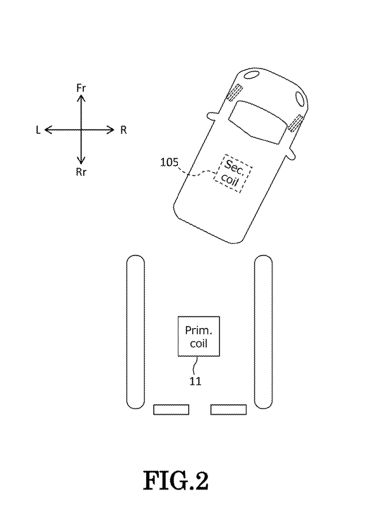
[0114]Hereinafter, an embodiment of the invention will be described by reference to the drawings. The drawings should be seen in a direction in which given reference numerals look normal. In the following description, front, rear, left, right, up and down denote accordingly directions as seen from a driver of a vehicle. The front, rear, left, right, up and down sides of the vehicle are denoted by Fr, Rr, L, R, U and D, respectively.

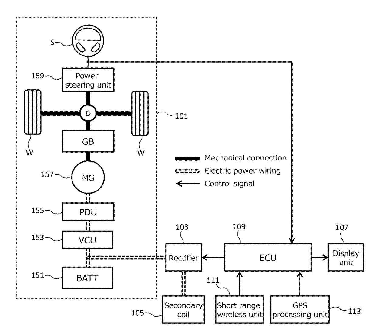
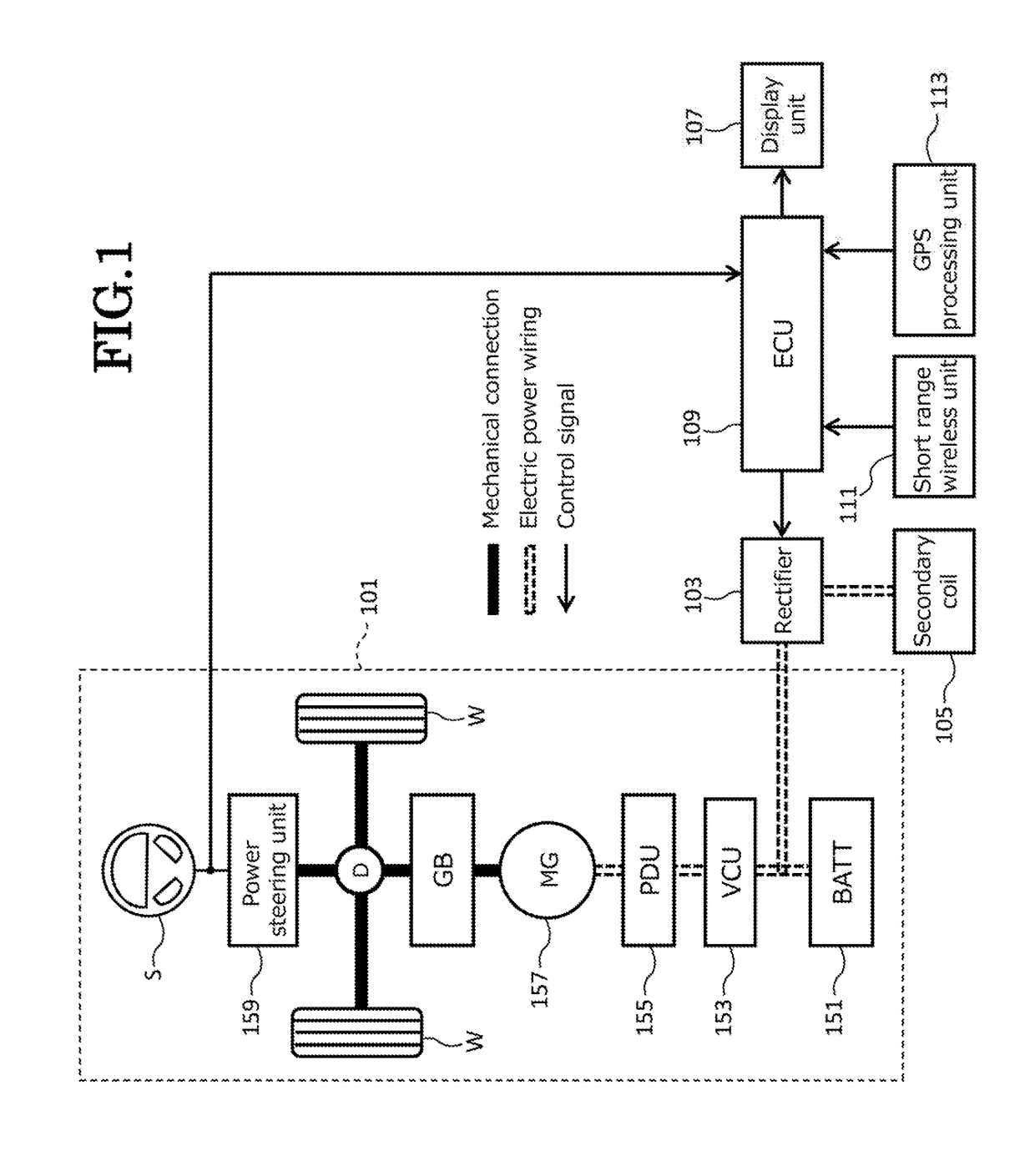
[0115]FIG. 1 is a block diagram showing a schematic configuration of an electric vehicle on which a power reception apparatus according to the invention is mounted. In FIG. 1, thick solid lines denote mechanical connections, double dotted lines denote electric power wiring, and thin solid lines with arrows denote control signals. An electric vehicle of a single motor type shown in FIG. 1 includes a drive part 101, a rectifier 103, a secondary coil 105, a display unit 107, an ECU 109, a short range wireless unit 111, and a GPS processing unit 113. Hereinaf...


PUM


Abstract

A power reception apparatus includes a secondary coil which receives electric power in a non-contact manner from a primary coil which is disposed on a plane defined by a front-rear direction and a left-right direction which are at right angles to each other, a drive part which can change a relative position on the plane of the secondary coil relative to the primary coil, a display unit, and a processing unit for processing an image to be displayed on the display unit. The processing unit displays the relative position and the gradient of the secondary coil on the display unit. A display mode which is used when the secondary coil is not included in the target zone in relation to the left-right direction is different from a display mode which is used when the secondary coil is included in the target zone in relation to the left-right direction.

Description

CROSS REFERENCE TO RELATED APPLICATIONS[0001]This application is based on Japanese Patent Application (No. 2016-089809) filed on Apr. 27, 2016, the contents of which are incorporated herein by reference.BACKGROUND OF THE INVENTION1. Field of the Invention[0002]The present invention relates to a power reception apparatus, vehicle, a power transmission apparatus, a power transmission and reception system, and a control method for supporting a positional alignment between a transmitting unit and a receiving unit before execution of power feeding using a non-contact power transmission technology (hereinafter, referred to as a “non-contact power feeding”).2. Description of the Related Art[0003]The industry has been focusing on the non-contact power transmission technology that takes the usability in charging into consideration as a technology for charging a battery installed on a vehicle such as a hybrid electric vehicle or an electric vehicle that is driven by an electric motor. In the ...

Claims


Application Information

Patent Timeline
Patent Type & Authority Applications(United States)
IPC IPC(8): B60L11/18H02J50/90
CPCB60L11/1829H02J50/90B60L11/1835H02J7/025B60L53/12B60L53/36B60L53/37B60L53/39B60L53/38B60L2210/30Y02T90/12Y02T10/7072Y02T90/14Y02T10/70
Inventor AMARI, YUSAKU
Owner HONDA MOTOR CO LTD
Why Eureka
Try Eureka