
Method for alignment of low-quality noisy depth map to the high-resolution colour image

a depth map and colour image technology, applied in image enhancement, image analysis, instruments, etc., can solve the problems of depth sensors that are prone to noise and other types of errors, source of noise, and the worsening of the sensed reflectan

Active Publication Date: 2017-11-02
NOKIA TECHNOLOGLES OY
View PDF0 Cites 61 Cited by
  • Summary
  • Abstract
  • Description
  • Claims
  • Application Information

AI Technical Summary

Benefits of technology

The patent describes a method and apparatus for obtaining a depth map of a scene using a camera and a depth sensor. The method involves obtaining a frame of an image of the scene and a frame of a depth map. Pixels in the image are then determined and projected to the depth layers to obtain a depth map. The cost values of the pixels in the depth map are filtered using color weights and the projected frame. The filtered cost values are then used to select a depth value for each pixel in the depth map. The technical effect of this patent is to provide a more accurate and precise depth map of a scene using a camera and depth sensor.

Problems solved by technology

Except lower resolution, depth sensors may also be prone to noise and other types of errors, including systematic errors.
Another source of noise in the time-of-flight cameras is connected with the power of illumination.
For instance, when using such camera in a mobile environment (e.g. as a handheld device), due to restricted power consumption infra-red emitters may not be able to illuminate with full power and hence, sensed reflectance may be worsen.
Other active depth sensors, such as based on the triangulation, may have depth errors connected with too sparse correlation pattern, which may result in wrong shapes of object boundaries and over-smoothing of small details.
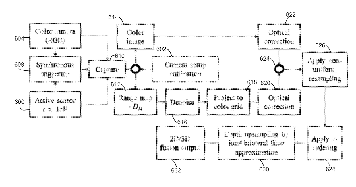
One problem appearing for many two-sensor 3D cameras is that it may not be possible to filter depth map using available colour image until it is aligned with a colour view and it is not possible to align a depth map before it was filtered.
Another problem, connected with the direct depth map projection is that a non-regular-to-regular grid resampling may be needed.

Method used


Image

  • Method for alignment of low-quality noisy depth map to the high-resolution colour image
  • Method for alignment of low-quality noisy depth map to the high-resolution colour image
  • Method for alignment of low-quality noisy depth map to the high-resolution colour image

Examples


Embodiment Construction

[0154]Example embodiments of the present invention will now be described more fully hereinafter with reference to the accompanying drawings, in which some, but not all embodiments of the invention are shown. Indeed, the invention may be embodied in many different forms and should not be construed as limited to the embodiments set forth herein; rather, these embodiments are provided so that this disclosure will satisfy applicable legal requirements. Like reference numerals refer to like elements throughout.

[0155]As used in this application, the term “circuitry” refers to all of the following: (a) hardware-only circuit implementations (such as implementations in only analog and / or digital circuitry) and (b) to combinations of circuits and software (and / or firmware), such as (as applicable): (i) to a combination of processor(s) or (ii) to portions of processor(s) / software (including digital signal processor(s)), software, and memory(ies) that work together to cause an apparatus, such a...


PUM


Abstract

Various embodiments are provided which relate to the field of image signal processing, specifically relating to the generation of a depth-view image of a scene from a set of input images of a scene taken at different cameras of a multi-view imaging system. A method comprises obtaining a frame of an image of a scene and a frame of a depth map regarding the frame of the image. A minimum depth and a maximum depth of the scene and a number of depth layers for the depth map are determined. Pixels of the image are projected to the depth layers to obtain projected pixels on the depth layers; and cost values for the projected pixels are determined. The cost values are filtered and a filtered cost value is selected from a layer to obtain a depth value of a pixel of an estimated depth map.

Description

TECHNOLOGICAL FIELD[0001]The various embodiments of the invention are related to the field of image signal processing, specifically relating to the generation of a depth-view image of a scene from a set of input images of a scene taken at different cameras of a multi-view imaging system.BACKGROUND[0002]Number of applications, such as three-dimensional (3D) and free-viewpoint TV, augmented reality, 3D visualization, 3D shape and colour scanning, simultaneous localization and mapping (SLAM), image segmentation and many others use view-plus-depth image format, which is also known as RGB+D format, as a main input source. In this format, each pixel of a digital colour image is augmented with the corresponding depth value, specifying distance between a corresponding point in the scene and the optical centre of the camera. Performance of these applications may directly depend on the quality of the supplied depth maps.[0003]Many consumer-level 3D cameras may have two camera sensors, one of ...

Claims


Application Information

Patent Timeline
Patent Type & Authority Applications(United States)
IPC IPC(8): G06T15/20G06T7/536H04N13/00G06T7/521G06T5/50G06T7/557G06T7/593G06T3/00G06T5/00H04N13/02G06T7/77
CPCG06T15/205G06T2207/30244G06T7/536G06T7/557G06T7/77H04N13/0055H04N13/0282G06T7/521G06T7/593G06T5/004G06T5/50G06T2215/16G06T2207/10024G06T2207/10028G06T2207/10052G06T2207/20024G06T2207/20221G06T3/0031G06T3/4007H04N2213/003H04N13/111H04N13/271H04N13/128H04N13/189H04N13/282G06T3/14G06T5/00H04N13/15G06T17/00H04N2013/0077H04N2013/0081H04N2013/0088G06T5/75G06T3/06
Inventor SMIRNOV, SERGEYGEORGIEV, MIHAILGOTCHEV, ATANAS
Owner NOKIA TECHNOLOGLES OY
Learn More