Solar Panel and Flexible Radiator for a Spacecraft

a solar array and flexible technology, applied in the direction of photovoltaics, cosmonautic components, cosmonautic parts, etc., can solve the problems of difficult to achieve the effect of reducing the area of spacecraft that is available for allocating solar collection and/or thermal dissipation functionality, and achieving the effect of simplifying the hold-down mechanism

Active Publication Date: 2017-11-09
AIRBUS DEFENCE & SPACE NETHERLANDS
View PDF17 Cites 5 Cited by
  • Summary
  • Abstract
  • Description
  • Claims
  • Application Information

AI Technical Summary

Benefits of technology

[0025]The overlapping arrangement of the radiator substrate and the solar array in the stowed state allows the use of a hold-down mechanism for simultaneously retaining both the solar ar...

Problems solved by technology

The area on a spacecraft that is available for allocating solar collection and/or thermal dissipation functionality may, however, be very limited.
This may be pa...

Method used


Image

  • Solar Panel and Flexible Radiator for a Spacecraft
  • Solar Panel and Flexible Radiator for a Spacecraft
  • Solar Panel and Flexible Radiator for a Spacecraft

Examples


Embodiment Construction

[0037]The following is a description of certain embodiments of the invention, given by way of example only and with reference to the figures. It should be understood that the directional definitions and preferred orientations presented herein merely serve to elucidate geometrical relations for specific embodiments. The concepts of the invention discussed herein are not limited to these directional definitions and preferred orientations. Similarly, directional terms in the specification and claims, such as “front”, “back / rear”, “top,”“bottom,”“left,”“right,”“up,”“down,”“upper,”“lower,”“proximal,”“distal” and the like, are used herein solely to indicate relative directions and are not otherwise intended to limit the scope of the invention or claims.

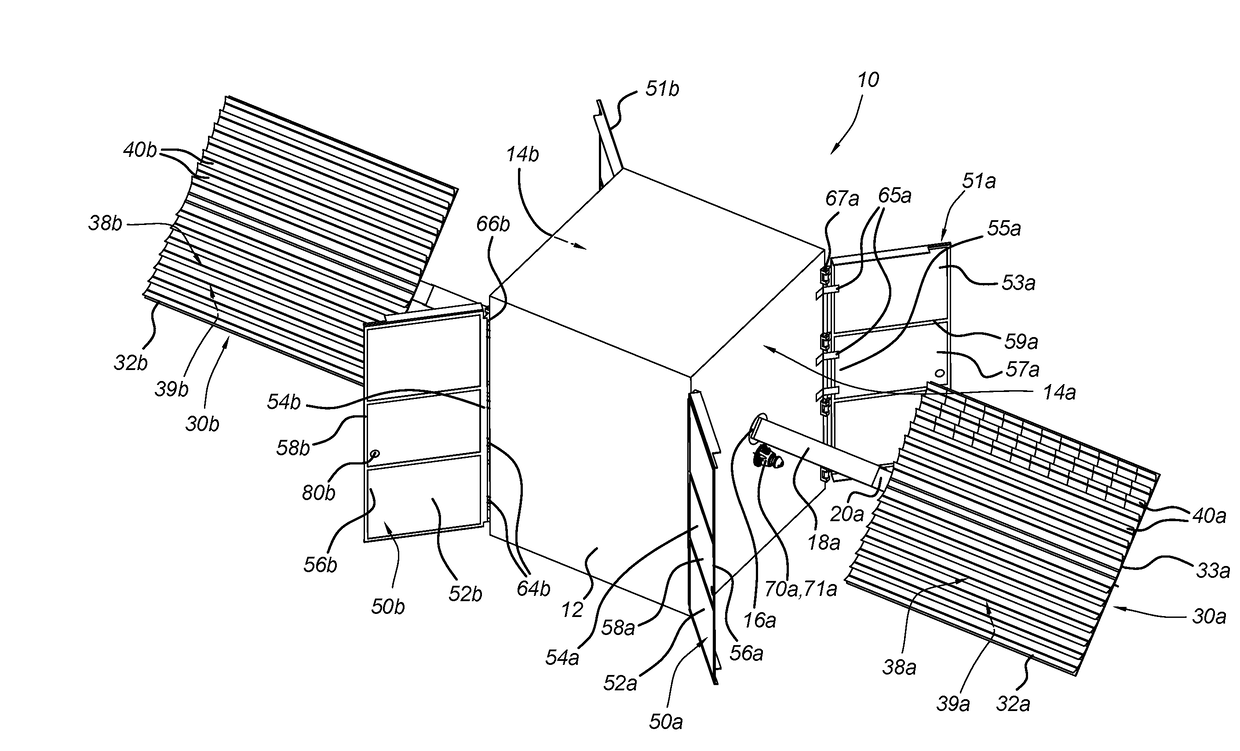
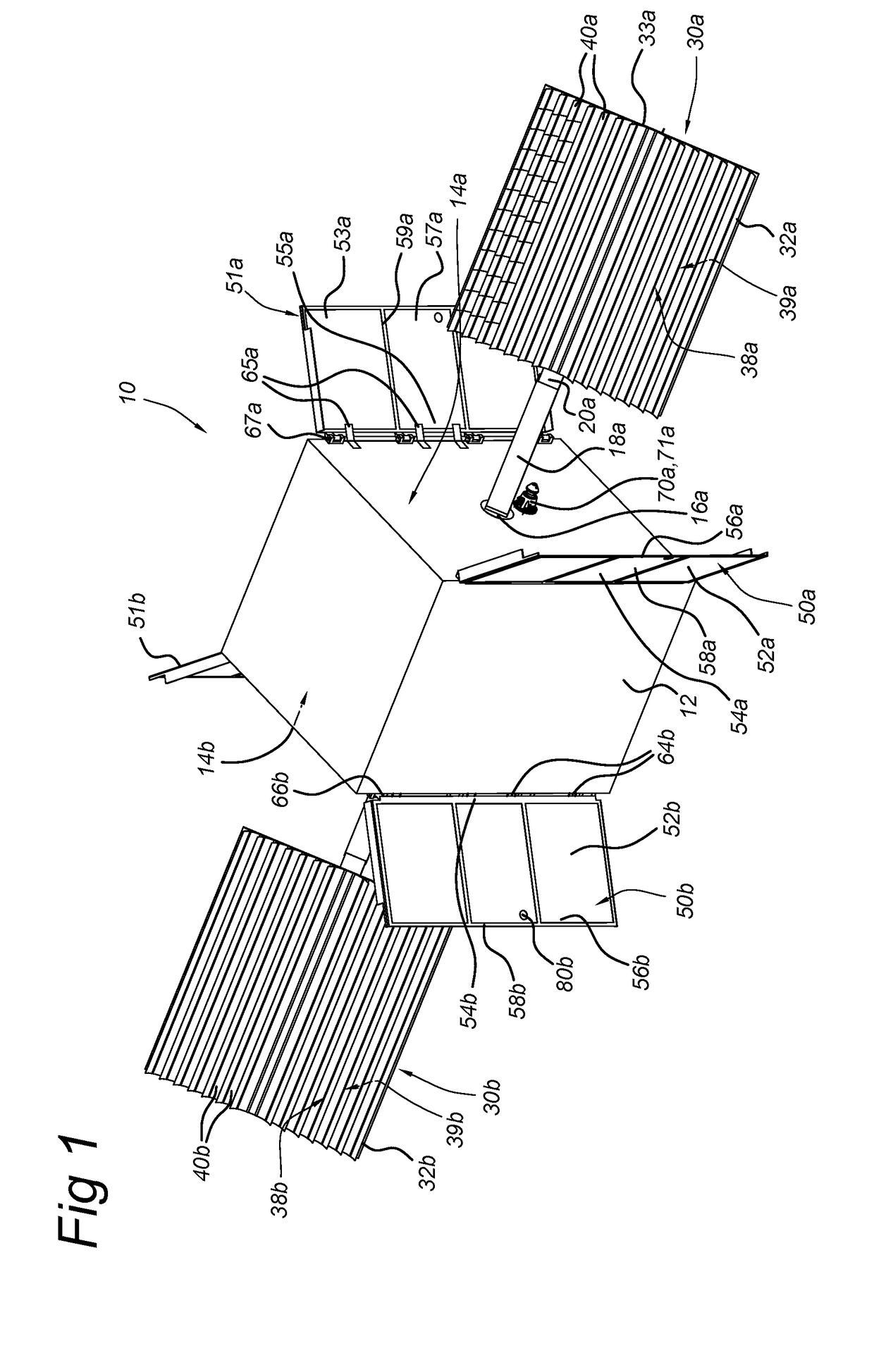
[0038]FIG. 1 schematically shows a perspective view of an embodiment of a spacecraft 10. In this example, the spacecraft is formed as a satellite unit 10. The satellite unit 10 includes a body 12, two solar arrays 30a, 30b, and four thermal...


PUM


Abstract

A spacecraft (10), comprising a body (12), a solar array (30) with a support panel (32) which is connected to the body, and a thermal radiator (50) that is connected to the body and which includes a radiator substrate (52) that is thermally coupled to the body via at least one heat link (64). The solar array and thermal radiator are configured to be transitioned from a stowed state wherein the support panel and the radiator substrate are held fixed in an overlapping arrangement along and near the body, to a deployed state wherein the solar array is unfolded with the support panel positioned at a distance from the body and the radiator substrate is folded away from the body and the solar array.
Preferably, the solar array and thermal radiator are flexible, to allow them to be kept in an overlapping and temporarily bent shape in the stowed state.

Description

TECHNICAL FIELD[0001]The invention relates to a combination of a solar array and a radiator for a spacecraft, and to a spacecraft provided with such a combination of a solar array and a radiator.BACKGROUND ART[0002]Solar arrays for use in or on spacecraft are known. Such solar arrays are typically used for powering the spacecraft based on photovoltaic (PV) conversion of solar radiation. Various solar cell arrangements for converting solar radiation into electricity have been proposed for space applications. Exemplary coupling and deployment mechanisms for solar panels are described in patent documents U.S. Pat. No. 6,091,016 and U.S. Pat. No. 6,031,178.[0003]It is also common to exploit thermal radiation in / on spacecraft to dissipate excess heat into space. This excess heat may be generated by various sources (e.g. power devices, equipment, or propulsion systems) in or on the spacecraft. Typically, excess heat is rejected via thermal radiation from the side walls of the spacecraft, ...

Claims


Application Information

Patent Timeline
IPC IPC(8): B64G1/44H01L31/0392H01L31/041H02S30/20H01L31/05H01L31/048
CPCB64G1/443H01L31/041H01L31/03926H01L31/048H01L31/0508H02S30/20B64G1/222B64G1/503Y02E10/50
Inventor CRUIJSSEN, JOHAN HENDRIKDATEMA, PETRUS CORNELISBENTHEM, BRUIN
Owner AIRBUS DEFENCE & SPACE NETHERLANDS
Why Eureka
Try Eureka