Azimuth determination with the aid of a radar sensor

a radar sensor and azimuth angle technology, applied in the direction of antenna details, instruments, antennas, etc., can solve the problem that the azimuth angle may only be determined with limited accuracy and separation capability

Active Publication Date: 2017-11-09
ROBERT BOSCH GMBH
View PDF1 Cites 15 Cited by
  • Summary
  • Abstract
  • Description
  • Claims
  • Application Information

AI Technical Summary

Benefits of technology

[0019]It is further preferred that the difference of the vertical height of the second receiving antenna to the heights of the first receiving antennas is less than the vertical extension of the second receiving antenna. It is particularly preferr...

Problems solved by technology

As the number of receiving antennas and the space available for the receiving antennas are usually limited, the azimuth angle may only be determined with limited accuracy and separation capability, and...

Method used


Image

  • Azimuth determination with the aid of a radar sensor
  • Azimuth determination with the aid of a radar sensor
  • Azimuth determination with the aid of a radar sensor

Examples


Embodiment Construction

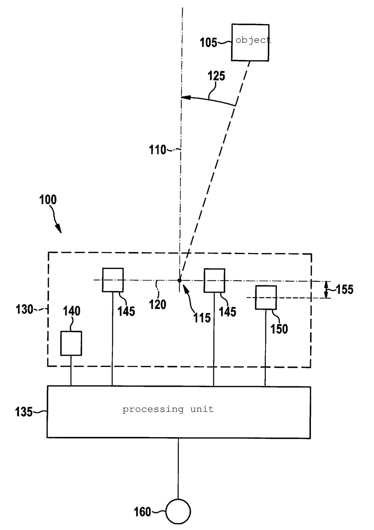
[0026]FIG. 1 shows an exemplary radar sensor 100 which may be configured for use on a motor vehicle. With the aid of radar sensor 100, the position of an object 105 is to be detected. An elevation angle, an azimuth angle, and a distance of object 105 are thereby usually determined. In another specific embodiment, a size or a movement of object 105 may also be determined. In the following, however, merely the determination of the azimuth angle of object 105 is described in greater detail. A coordinate system is assumed for this purpose which is extended with respect to the motor vehicle. The coordinate system includes a longitudinal axis 110, a vertical axis 115, and a transverse axis 120 which intersect at a shared point and in pairs with one another describe angles of 90°. An azimuth angle 125 of object 105 is indicated by way of example in FIG. 1.

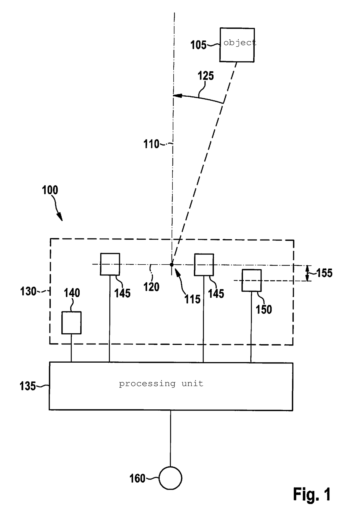
[0027]Radar sensor 100 includes, for example, an arrangement 130 and a processing unit 135. Antenna arrangement 130 generally includes a...


PUM


Abstract

A radar sensor includes one transmitting antenna, multiple first receiving antennas with the same vertical heights, and a second receiving antenna with a vertical height different from the others. A method for determining the azimuth angle of an object with respect to the radar sensor includes steps of determining an approximation for the azimuth angle in a coarse grid based on the signals of all receiving antennas, and determining the azimuth angle in a fine grid based on the signals of the first receiving antennas in a range around the approximation.

Description

CROSS REFERENCE[0001]The present application claims the benefit under 35 U.S.C. §119 of German Patent Application No. DE 102016207871.2 filed on May 9, 2016, which is expressly incorporated herein by reference in its entirety.BACKGROUND INFORMATION[0002]A relative position of an object with respect to a radar sensor may be determined in that a radar signal is transmitted by the radar sensor and its reflection at the object is received again. The position of the object is generally indicated based on an elevation angle, an azimuth angle, and a distance. For example, a radar sensor may be used on a motor vehicle to detect objects located ahead of the motor vehicle in the driving direction. A coordinate system fixed to the motor vehicle is thereby usually assumed. The azimuth angle is usually determined by the vertical axis with respect to a longitudinal axis of the motor vehicle. Correspondingly, the elevation angle is determined by the transverse axis with respect to the longitudinal...

Claims


Application Information

Patent Timeline
IPC IPC(8): G01S13/06G01S13/93G01S13/931
CPCG01S13/931G01S13/06G01S13/42G01S7/032H01Q1/3233H01Q21/065
Inventor LOESCH, BENEDIKTGROSS, VOLKER
Owner ROBERT BOSCH GMBH
Why Eureka
Try Eureka