

Communication process and system for high-sensitivity and synchronous demodulation signals
- Summary
- Abstract
- Description
- Claims
- Application Information
AI Technical Summary
Benefits of technology
Problems solved by technology
Method used
Image

Examples
first embodiment
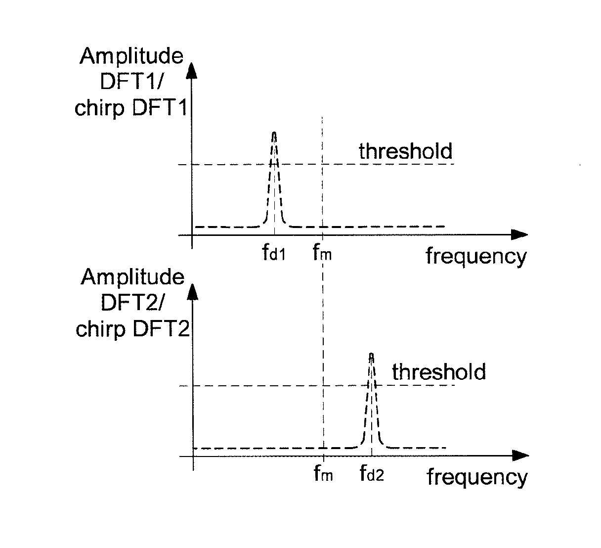
[0059]In this first embodiment, the logic unit 37 comprises an assembly 38 of m pairs of discrete Fourier transform blocks, chirp DFT1 and chirp DFT2, which are arranged for operation in parallel. The number m is higher than or equal to 1 and it should be noted that the higher the number m, the quicker the synchronisation phase becomes with fewer successive acquisitions. A first chirp block DFT1 of each pair is provided for the acquisition in relation to the positive slope of frequency variation of the captured chirp signal. This acquisition by the first chirp block DFT1 operates in a first half-cycle of the duration of a frequency variation cycle of the chirp signal, i.e. of the intermediate signal IF. A second chirp block DFT2 of each pair is provided for the acquisition in relation to the negative slope of frequency variation of the captured chirp signal. This acquisition by the second chirp block DFT2 operates in a second half-cycle of the duration of a frequency variation cycle...
second embodiment
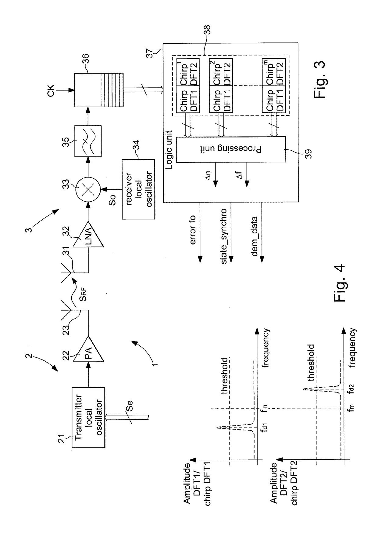
[0072]FIG. 7 shows the communication system 1 for implementing the communication process. As the majority of the components are identical to the communication system described with reference to FIG. 3, these component will not be described. It is principally the components of the logic unit 37 and their function that will be described.
[0073]The logic unit 37 receives the sampled signal coming from the sampler 36 in order to determine a frequency error f0, a synchronisation state, a demodulation of the data. Only one assembly 38′ with two discrete Fourier transform blocks DFT1 and DFT2 is provided in the logic unit 37. As mentioned above, a first block DFT1 performs a DFT projection on a core of n vectors for the first half-cycle of acquisition of the positive slope of frequency variation. A second block DFT2 performs a DFT projection on a core of n vectors for the second half-cycle of acquisition of the negative slope of frequency variation. A single calculation is performed at the ...
PUM
 Abstract
Description
Claims
Application Information