Transfer roller, and production method for the transfer roller

a technology of transfer roller and production method, which is applied in the field of transfer roller, can solve the problem of inability to produce a transfer roller with a lower rubber hardness, and achieve the effect of reducing rubber hardness and reducing foam cell diameter

Inactive Publication Date: 2017-11-16
SUMITOMO RUBBER IND LTD
View PDF4 Cites 0 Cited by
  • Summary
  • Abstract
  • Description
  • Claims
  • Application Information

AI Technical Summary

Benefits of technology

[0022]According to the present invention, the transfer roller is provided which is flexible with a lower rubber hardness and has smaller foam cell diameters. The production methods for the transfer roller are also provided.

Problems solved by technology

If OBSH is used alone as the foaming agent, therefore, it is impossible to produce a transfer roller which is flexible with a lower rubber hardness and has smaller foam cell diameters to satisfy the recent requirements.

Method used


Image

  • Transfer roller, and production method for the transfer roller
  • Transfer roller, and production method for the transfer roller

Examples


example 1

Conventional Example 1

[0163]An electrically conductive rubber composition was prepared and a transfer roller 1 was produced in substantially the same manner as in Example 1, except that sodium hydrogen carbonate was not blended.

example 2

Conventional Example 2

[0164]A transfer roller 1 was produced in substantially the same manner as in Example 1, except that the tubular body formed in Example 1 was pressurized and heated at 135° C. for 10 minutes in a vulcanization can by pressurized steam in a first-stage foaming step and then pressurized and heated at 165° C. for 3 hours in the vulcanization can by pressurized steam in a second-stage foaming step.

[0165]Conventional Example 2 corresponds to the roller produced by the method described in Patent Document 2 by using OBSH and sodium hydrogen carbonate in combination as the foaming agent, and foaming and crosslinking the tubular body in the vulcanization can without the use of a mold in the first-stage crosslinking step.

[0166]The Asker-C hardness of each of the transfer rollers 1 produced in Examples 1 to 3, Comparative Examples 1 and 2 and Conventional Examples 1 and 2 was measured by the aforementioned measurement method. A transfer roller having an Asker-C hardness o...

example 4

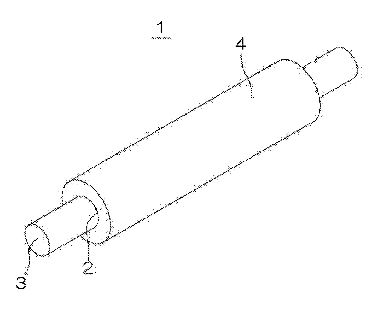
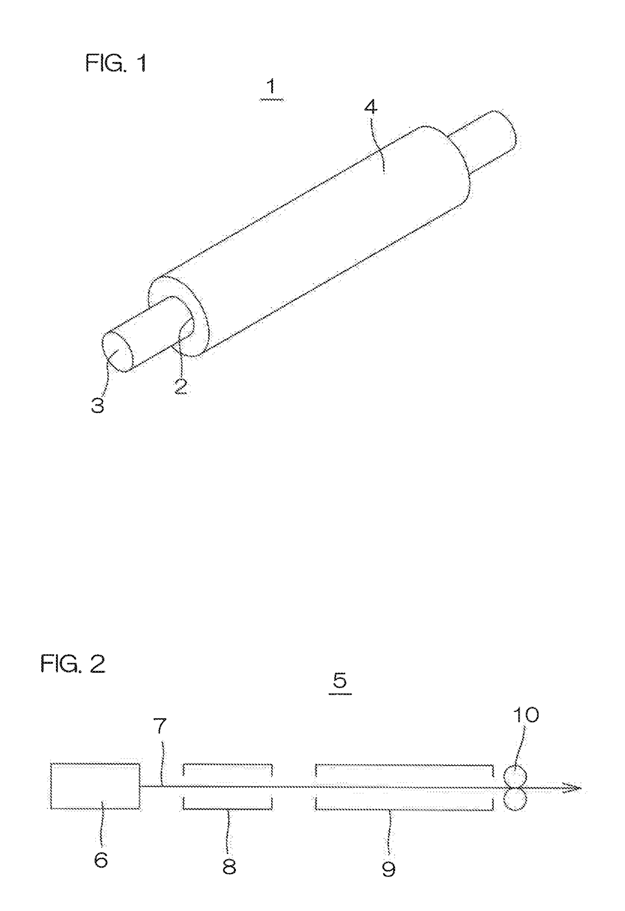
[0172]The electrically conductive rubber composition prepared in Example 1 was formed into a ribbon shape, and continuously fed into an extruder 6 to be extruded into an elongated tubular body 7 having an outer diameter of 10 mm and an inner diameter of 3.0 mm. The tubular body 7 formed by the extrusion was continuously fed out in an elongated state without cutting to be continuously passed through the continuous crosslinking apparatus 5 including the microwave crosslinking device 8 and the hot air crosslinking device 9, whereby the rubber component of the tubular body was continuously foamed and crosslinked. Then, the resulting tubular body was passed through cooling water to be continuously cooled.

[0173]The microwave crosslinking device 8 had an output of 6 to 12 kW and an internal control temperature of 135° C. The hot air crosslinking device 9 had an internal control temperature of 135° C. and an effective heating chamber length of 8 m.

[0174]In turn, the tubular body was cut to ...


PUM

PropertyMeasurementUnit
cell diameteraaaaaaaaaa
average cell diameteraaaaaaaaaa
temperatureaaaaaaaaaa

Abstract

An inventive transfer roller (1) is made of a foam formed from an electrically conductive rubber composition containing an electrically conductive rubber, a crosslinking component, and a foaming agent including OBSH and 0.25 to 2.5 parts by mass of sodium hydrogen carbonate based on 1 part by mass of OBSH, and has an Asker-C hardness of not lower than 25 degrees and not higher than 35 degrees and an average foam cell diameter of not greater than 120 μm. Therefore, the transfer roller is flexible with a lower rubber hardness, and has smaller foam cell diameters. An inventive production method includes the steps of: forming the electrically conductive rubber composition into a tubular body; and maintaining the tubular body at a temperature of not lower than 120° C. and not higher than 140° C. to foam the rubber by a single-stage foaming process.

Description

TECHNICAL FIELD[0001]The present invention relates to a transfer roller, and to a production method for the transfer roller.BACKGROUND ART[0002]In an electrophotographic image forming apparatus such as a laser printer, an electrostatic copying machine, a plain paper facsimile machine or a printer-copier-facsimile multifunction machine, an image is generally formed on a surface of a sheet such as a paper sheet or a plastic film through the following process steps.[0003]First, a photoelectrically conductive surface of a photoreceptor body is evenly electrically charged (charging step). Then, the surface of the photoreceptor body is exposed to light, whereby an electrostatic latent image corresponding to an image to be formed on the sheet is formed on the surface of the photoreceptor body (exposing step).[0004]In turn, toner (minute color particles) preliminarily electrically charged at a predetermined potential is brought into contact with the surface of the photoreceptor body. Thus, ...

Claims


Application Information

Patent Timeline
Patent Type & Authority Applications(United States)
IPC IPC(8): G03G15/16B29C47/88B29C47/00B29C48/09B29K33/18B29K507/04B29L31/00
CPCG03G15/162B29C47/881B29C47/0042B29C47/0023B29K2033/18B29L2031/767B29K2995/0005B29K2995/007B29K2507/04C08J9/08C08J9/105C08L71/02C08J2423/16C08J2203/18C08J2371/02C08J2203/04C08J2203/02C08L2312/00C08L2205/035C08L23/16C08L9/02C08L91/00C08K13/02C08K3/04C08K3/26C08K3/06G03G15/1685B29C48/001B29C48/09B29C48/0012B29C48/9105
Inventor TANIO, YUSUKE
Owner SUMITOMO RUBBER IND LTD
Why Eureka
Try Eureka