
Method to assemble aperture segments of a cylindrical feed antenna

a cylindrical, aperture-type technology, applied in the direction of individual energised antenna arrays, feed arrays, linear waveguide fed arrays, etc., can solve the problems of affecting the set throughput of the manufacturing line, tft/lc aperture fabrication utilizes some processes that are not easily accommodated by existing tft/lcd fabrication facilities, and large capital outlay of building such a facility and populating it with equipmen

Active Publication Date: 2017-11-16
KYMETA
View PDF0 Cites 14 Cited by
  • Summary
  • Abstract
  • Description
  • Claims
  • Application Information

AI Technical Summary

Benefits of technology

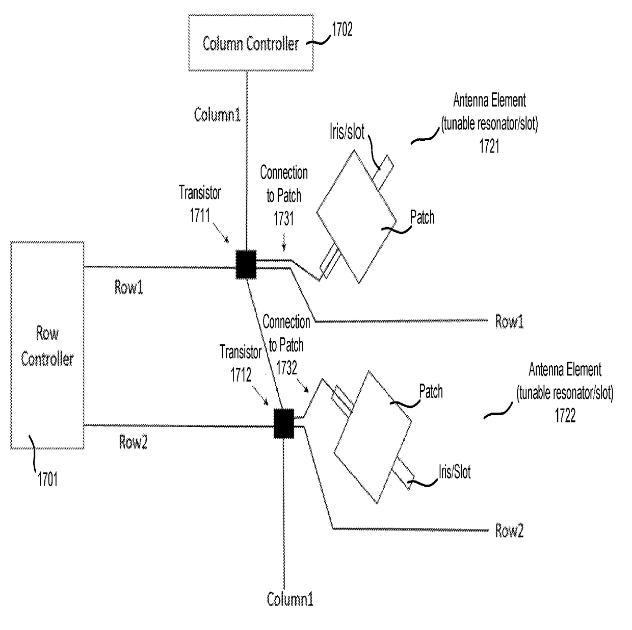
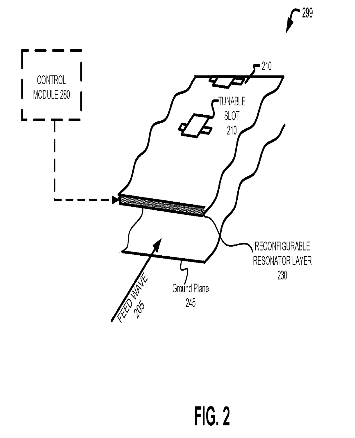
The present patent application claims priority to a provisional patent application filed on May 10, 2016, and describes a method to assemble an aperture segment to create a cylindrical feed antenna aperture. The invention aims to improve the efficiency and reduce the cost impact of manufacturing a TFT / LC aperture by mitigating the impact of unbalancing the line and adding capacity in the manufacturing process. The invention proposes the use of a coaxial feed, antenna elements placed in concentric rings around an input feed, and a tunable resonator / slot. The invention also suggests the use of small aperture segments and the application of a matrix drive lattice to further improve the efficiency and reduce the cost of manufacturing the TFT / LC aperture.

Problems solved by technology

Therefore, the capital outlay of building such a facility and populating it with equipment is very large.
Unfortunately, TFT / LC aperture fabrication utilizes some processes that are not easily accommodated by existing TFT / LCD fabrication facilities.
That is, by performing these steps, the fabrication facility, line, etc. are disrupted, harming the set throughput of the manufacturing line.
Therefore, making an antenna aperture with a single TFT / LC panel is inefficient, reduces fabrication throughput, and significantly raises the manufacturing costs of the resulting TFT / LC aperture.
For a recent generation TFT / LC facility, with a mother glass capable of making the TFT / LC RF aperture in one piece, this capital outlay would be prohibitively large.
Due to underutilization and the depreciated nature of such fabrication facilities, the impact of unbalancing the line is not as expensive as in a more recent generation fabrication facility.
Additionally, building capacity in the required steps is not as capital intensive due to the smaller sizes of the mother glass.
However, the mother glass sizes of these older generation fabrication facilities are not large enough to build the TFT / LC RF apertures on one mother glass.

Method used


Image

  • Method to assemble aperture segments of a cylindrical feed antenna
  • Method to assemble aperture segments of a cylindrical feed antenna
  • Method to assemble aperture segments of a cylindrical feed antenna

Examples


an example system embodiment

[0155]In one embodiment, the combined segments forming an aperture can be used in a television system that operates in conjunction with a set top box. For example, in the case of a dual reception antenna, satellite signals received by an antenna utilizing one or more of the formed apertures are provided to a set top box (e.g., a DirecTV receiver) of a television system. More specifically, the combined antenna operation is able to simultaneously receive RF signals at two different frequencies and / or polarizations. That is, one sub-array of elements is controlled to receive RF signals at one frequency and / or polarization, while another sub-array is controlled to receive signals at another, different frequency and / or polarization. These differences in frequency or polarization represent different channels being received by the television system. Similarly, the two antenna arrays can be controlled for two different beam positions to receive channels from two different locations (e.g., t...


PUM

PropertyMeasurementUnit
anglesaaaaaaaaaa
free-space wavelengthaaaaaaaaaa

Abstract

A method of assembling an antenna aperture from a plurality of antenna aperture segments is described. The method may include placing a first aperture segment relative to a second aperture segment to partially form the antenna aperture. Furthermore, an overlap of the first aperture segment overlaps a complementary underlap of the second aperture segment at a seam. The method may also include joining the overlap of the first aperture segment to the underlap of the second aperture segment to partially form the antenna aperture.

Description

PRIORITY[0001]The present patent application claims priority to and incorporates by reference the corresponding provisional patent application Ser. No. 62 / 334,231, titled, “METHOD TO ASSEMBLE APERTURE SEGMENTS OF A CYLINDRICAL FEED ANTENNA,” filed on May 10, 2016.FIELD[0002]Embodiments of the invention relate to antennas for wireless communication; more particularly, embodiments of assembly of the invention relate to assembly of aperture segments to generate a-cylindrical feed antenna aperture.BACKGROUND OF THE INVENTION[0003]Thin-film-transistor (TFT) / liquid crystal (LC) antenna apertures may be formed in a single TFT / LC panel. This requires that the mother glass in the TFT / LC panel fabrication be large enough to accommodate the entire active area, the routing, connection area, seal area, etc. A TFT / LC fabrication facility is a highly tuned line of machinery that operates efficiently at a set throughput, with all equipment in the line matched to this throughput. Therefore, the capi...

Claims


Application Information

Patent Timeline
Patent Type & Authority Applications(United States)
IPC IPC(8): H01Q3/36H01Q21/00H01Q19/17H01Q3/40H01Q3/28H01Q21/20H01Q3/24
CPCH01Q3/36H01Q19/175H01Q3/242H01Q3/28H01Q21/205H01Q3/40H01Q21/005H01Q21/0012H01Q21/0025H01Q15/0086H01Q21/0087H01Q21/20H01Q21/293H05K13/0469Y10T29/49016Y10T29/49131
Inventor LINN, STEVENMOREY, ROBERTOLFERT, STEPHENTURNER, ANDREWRILEY, MATTHEWMALLARI, JONATHANSHORT, COLIN STUART
Owner KYMETA
Learn More