Phased array antenna choke plate method and apparatus

a phased array and choke plate technology, applied in the direction of antennas, antenna details, antenna adaptation in movable bodies, etc., can solve the problems of significant aperture size, design generally not meeting, and the solution is not acceptable for high-speed aircraft installation

Active Publication Date: 2007-11-13
THE BOEING CO
View PDF5 Cites 30 Cited by
  • Summary
  • Abstract
  • Description
  • Claims
  • Application Information

AI Technical Summary

Benefits of technology

[0007]The present invention involves an antenna system incorporating a choke plate and method for attenuating radio frequency (RF) sidelobes of an antenna mounted externally on an aircraft, where RF interference considerations with terrestrial-based RF networks is important. The choke apparatus of the present invention sufficiently attenuates the sidelobes of the antenna aperture with which it is used to avoid significant RF radiation below the horizon when an airborne mobile platform on which the antenna system is in flight.
[0008]In one preferred form, the choke apparatus comprises a choke plate and a plurality of parallel grooves formed in a surface thereof. In one preferred form the grooves are formed in an upper surface and are arranged in a plurality of groups. The choke plate includes an opening within which the antenna aperture resides, such that the aperture is at least substantially circumscribed by the choke plate. The grooves on the choke plate may be filled with a dielectric to further tune the performance of the choke plate, as well as to provide a more aerodynamic surface.
[0009]The choke plate is suitable for use on high-speed mobile platforms, such as commercial jet aircraft, without tangibly degrading the aerodynamic performance of the aircraft.

Problems solved by technology

To achieve broadband data rates, a high-gain antenna is typically required, resulting in a significant aperture size.
At a cruise altitude represented by line A, the sidelobe radiation of a crown-mounted antenna may irradiate the Earth, as represented by arc B. The sidelobe attenuation needs to be sufficient such that substantially no radiation extends beyond the arc labeled C. Current designs generally do not meet these requirements.
This solution has not been acceptable for high-speed aircraft installations because such choke designs are exposed to the air stream and are susceptible to environmental issues such as corrosion and debris contamination.
Such structures also have detrimental or unacceptable effects on aerodynamic drag, noise and vibration.

Method used


Image

  • Phased array antenna choke plate method and apparatus
  • Phased array antenna choke plate method and apparatus
  • Phased array antenna choke plate method and apparatus

Examples


Embodiment Construction

[0035]The following description of the preferred embodiment(s) is merely exemplary in nature and is in no way intended to limit the invention, its application, or uses.

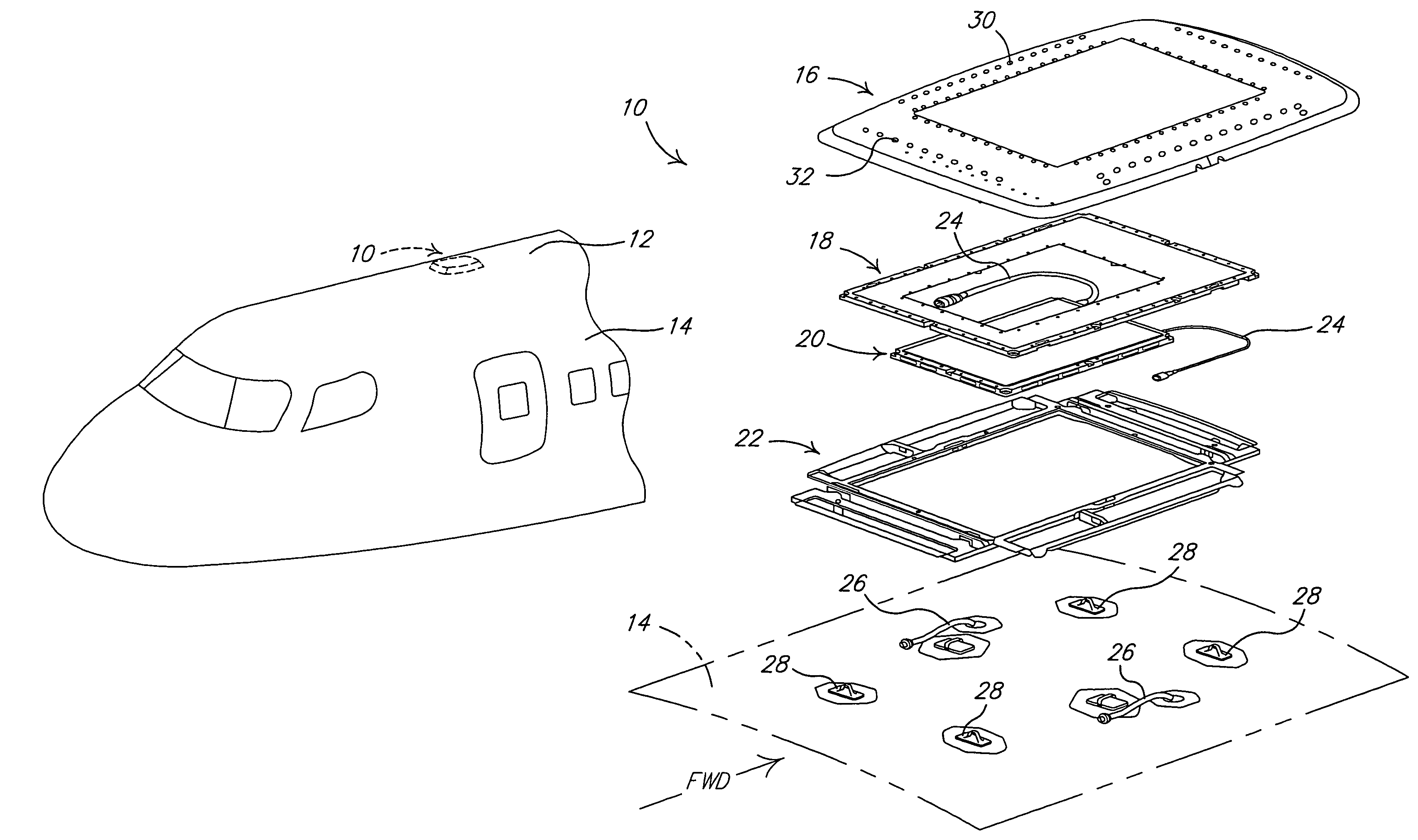
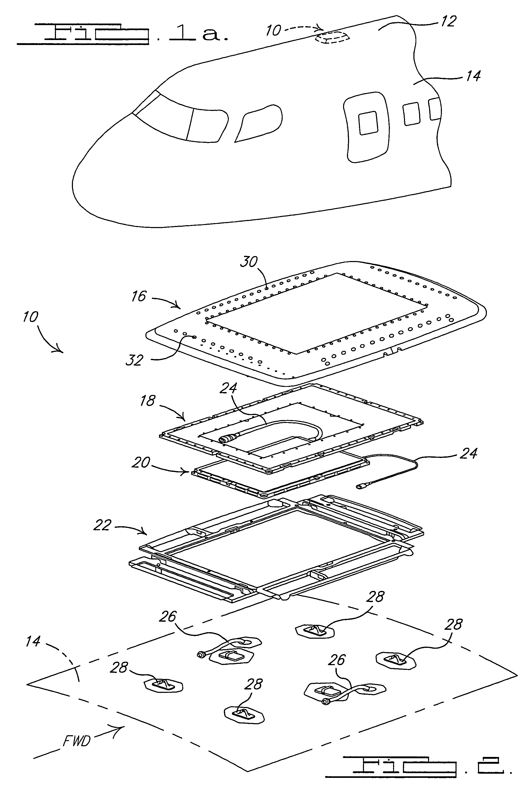
[0036]Referring to FIG. 1a, there is shown an antenna system 10 in accordance with a preferred embodiment of the present invention. The antenna system 10 is located, in this example, on an external surface of a mobile platform 12. In this example, the mobile platform 12 forms a commercial aircraft, and the antenna system 10 is located on an external surface of the fuselage 14 on the crown of the fuselage. It will be appreciated, however, that the antenna system 10 could be used on any form of airborne mobile platform, or possibly even on any form of marine vessel or land vehicle. Essentially, any vehicle having an antenna mounted thereon where controlling the sidelobes of the beam projected from the antenna is an important consideration, could potentially make use of the invention.

[0037]Referring now to FIG. 2, antenn...


PUM


Abstract

A phased array antenna system on an aircraft that incorporates a choke plate that significantly attenuates sidelobes of the antenna beam pattern at elevation angles that would cause RF interference with ground-based terrestrial wireless networks. The choke plate includes a plurality of choke grooves that substantially circumscribe the antenna aperture. The choke plate has an upper surface that is positioned generally coplanar with the upper surface of the antenna aperture. The grooves of the choke plate may be filled with a dielectric material. The choke plate provides a smooth aerodynamic component that significantly attenuates beam scattering, and thus the radiation pattern sidelobes of the antenna at or below the horizon, when the aircraft is in flight.

Description

CROSS-REFERENCE TO RELATED APPLICATIONS[0001]This application claims priority to U.S. provisional application No. 60 / 673,846 filed on Apr. 22, 2005, the disclosure of which is incorporated herein by reference.FIELD OF THE INVENTION[0002]The present invention relates to phased array antennas. More specifically, this invention relates to structures and method for controlling the shape of the radiation pattern side lobe features of antennas, and particularly phased array antennas.BACKGROUND OF THE INVENTION[0003]Airborne satellite communication systems generally require an externally-mounted antenna unit. To achieve broadband data rates, a high-gain antenna is typically required, resulting in a significant aperture size. This structure is typically mounted on the top of the mobile platform, for example, on the crown of the fuselage of an aircraft. The structure is typically covered by an aerodynamically-shaped fairing having small frontal areas. Additional requirements are imposed by r...

Claims


Application Information

Patent Timeline
Patent Type & Authority Patents(United States)
IPC IPC(8): H01Q1/28
CPCH01Q1/286H01Q19/021H01Q13/0266
Inventor FERGUSON, STANLEY DRASMUSSEN, DAVID NTAYLOR, MICHAEL J
Owner THE BOEING CO
Why Eureka
Try Eureka