Dual frequency antenna aperture

a dual-frequency antenna and aperture technology, applied in the direction of resonant antennas, instruments, reradiation, etc., can solve the problems of complex feeding network interfering with the bottom planar array antenna, complicated frequency selective surface for radiating elements and ground plane, and antennas being required

Active Publication Date: 2011-12-29
SAAB AB
View PDF8 Cites 27 Cited by
  • Summary
  • Abstract
  • Description
  • Claims
  • Application Information

AI Technical Summary

Problems solved by technology

A drawback with this solution is that a rather complicated frequency selective surface for the radiating elements and ground plane of the top planar array antenna is required.
A further drawback is that each antenna element in the top planar array antenna requires an individual feed, resulting in a complicated feeding network interfering with the bottom planar array antenna.
The solution also has the limitation of using only patch elements in both bottom and top planar array antenna.
In practice, the limited size will cause edge effects that will degrade the performance.
This is a fairly complicated solution resulting in disturbances between the top and bottom planar array antennas degrading the high frequency performance.
The slots and dipoles are located in the same plane which creates a risk for interference between the two types of antenna elements.
The feeding of the dipoles is complicated and / or includes parts of the feeding structure being parallel or almost parallel to the polarization of the slots.
This feeding structure also increases the risk of increased interference between the different types of antenna elements.
Furthermore, the substrate, used as a carrier for the microstrip transmission lines, will add losses to the slot antenna since it is located very close to the slot apertures.

Method used


Image

  • Dual frequency antenna aperture
  • Dual frequency antenna aperture
  • Dual frequency antenna aperture

Examples


Embodiment Construction

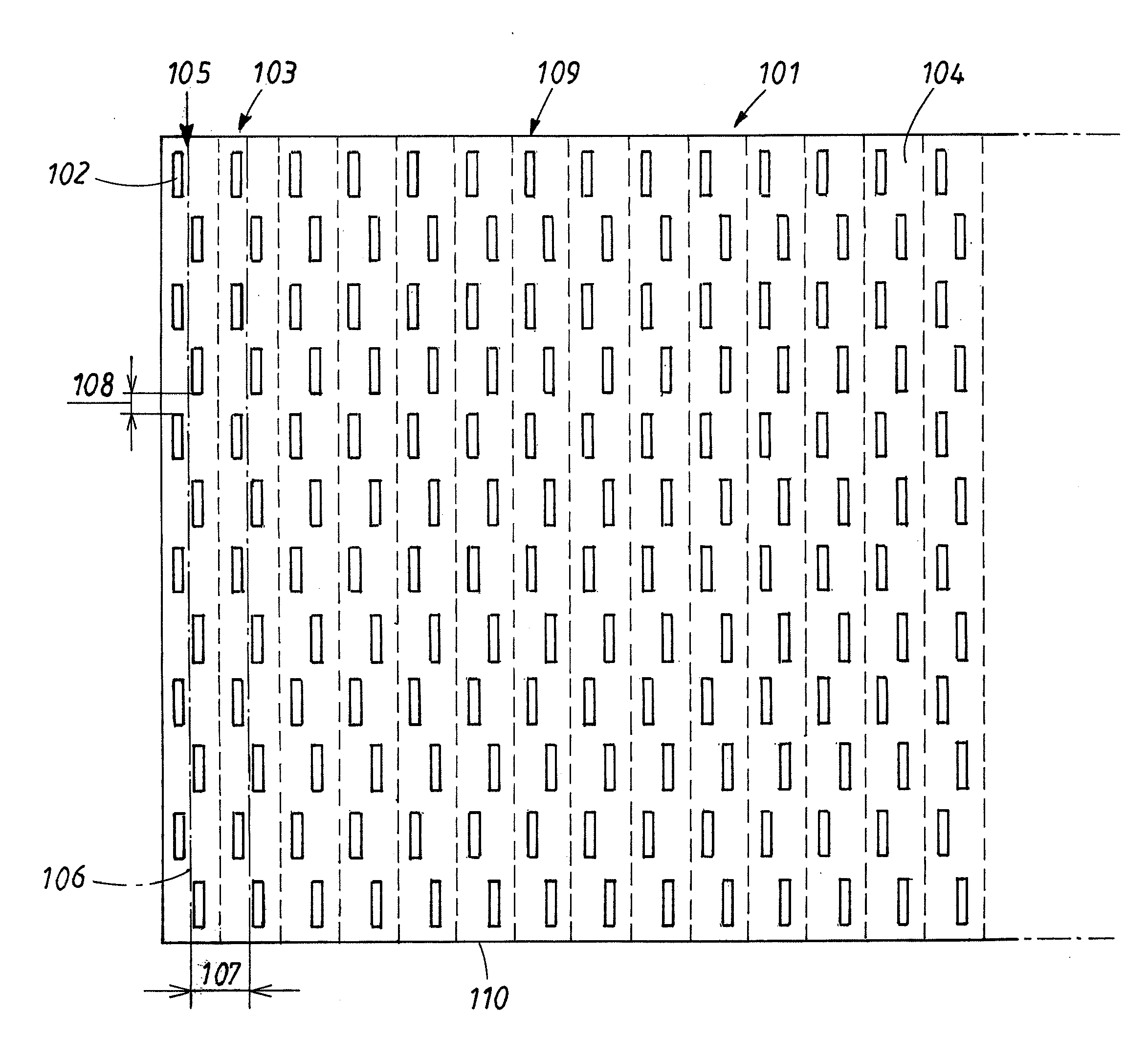
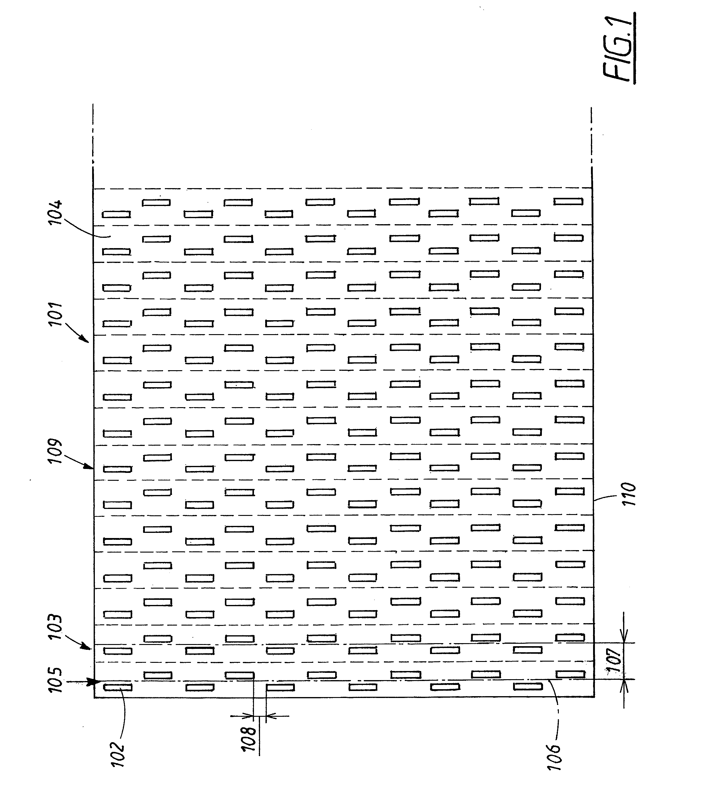
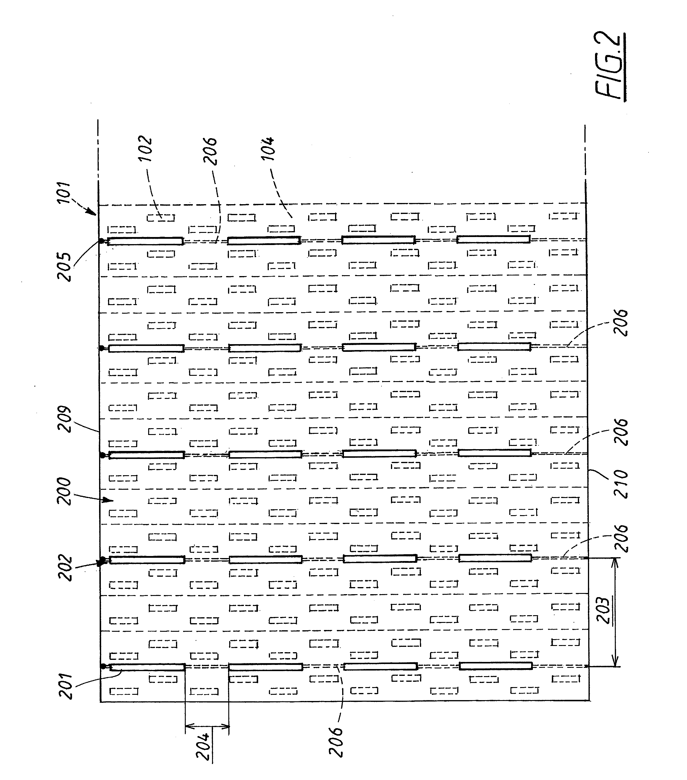
[0021]The invention will now be described in detail with reference to the drawings.

[0022]The invention is applicable in general to antennas for radio communication or radar system requiring two antenna apertures working at different frequency bands. Henceforth in the description the invention is exemplified with a radar system requiring one antenna aperture for a PSR antenna operating at a certain high frequency and one antenna aperture for an IFF / SSR antenna operating at a certain lower frequency. Other combinations of one high and one low frequency band are possible within the scope of the invention. A typical application can be a high frequency of one to several GHz, the high frequency being 3-4 times higher than the low frequency. In this example certain directions of slots, columns and polarizations are defined as vertical and horizontal. The invention is however applicable to other directions as long the two directions are substantially perpendicular.

[0023]When a certain apert...


PUM

PropertyMeasurementUnit
relative dielectric constantaaaaaaaaaa
frequency bandaaaaaaaaaa
areaaaaaaaaaaa

Abstract

An antenna structure including at least two stacked antenna apertures, a first antenna aperture with first antenna elements and at least a second antenna aperture with second antenna elements. The antenna structure is arranged for operation in at least a high and a low frequency band. The first antenna elements are arranged for operation in the high frequency band and the second antenna elements for operation in the low frequency band. The first antenna elements are arranged to have a polarization substantially perpendicular to the polarization of the second antenna elements. The second antenna elements are arranged in at least one group and each of the group includes a number of second antenna elements coupled in series and arranged to have a common feeding point on a straight feeding structure. One feeding structure is located adjacent to each group of second antenna elements. The direction of the feeding structure is substantially perpendicular to the polarization of the first antenna elements. A corresponding method and a radar system including the antenna structure.

Description

TECHNICAL FIELD[0001]The present invention relates to the field of antennas for radio communication and radar systems.BACKGROUND ART[0002]A surveillance radar system comprises a Primary Surveillance Radar (PSR) and an Identification Friend or Foe / Secondary Surveillance Radar (IFF / SSR). In prior art solutions, the IFF / SSR-antenna system typically consists of one or more separate antennas.[0003]In a radar surveillance system, the PSR antenna will have a very narrow, main beam and extremely low side lobes. The IFF / SSR antenna has an operating frequency which normally is a few times lower than the operating frequency of the PSR. It is normally desired to have as large aperture as possible, measured in wavelengths, for both functions. One standard solution is to have two separate antenna apertures, which means an overall antenna system size, being the sum of the two antenna apertures. It would be desirable to use an increased aperture for the IFF / SSR-antenna without substantially increas...

Claims


Application Information

Patent Timeline
Patent Type & Authority Applications(United States)
IPC IPC(8): G01S13/00H01P11/00H01Q13/10
CPCY10T29/49016H01Q9/16H01Q13/08H01Q13/10H01Q21/28H01Q9/28
Inventor SVENSSON
Owner SAAB AB
Why Eureka
Try Eureka