Transection device

a transverse device and a technology for tracing, which are applied in the field of transverse devices, can solve the problems of affecting the functionality of the connection to the body, irregular and difficult management, excessive handling, etc., and achieves the effects of facilitating the management of the anastomose, reducing complications, and saving time in the operation

Active Publication Date: 2017-11-23
RUTGERS THE STATE UNIV
View PDF8 Cites 15 Cited by
  • Summary
  • Abstract
  • Description
  • Claims
  • Application Information

AI Technical Summary

Benefits of technology

[0004]In at least one aspect of the present disclosure, the device described herein may be utilized to create the “cuffs” for the hepatic artery and bile stumps in a more precise manner which will facilitate management of these anastomoses while potentially saving time in performing the procedure and resulting in fewer complications related to these connections. While the specific use of the device described herein is the transaction of delicate tubular structures in the setting of liver (hepatic artery and bile duct), kidney (ureter) and any solid organ transplant, it is recognized that the device may be configured for a wide range of applications, for example, in vascular and other surgical settings other than those related to transplantation. Furthermore, the device is not limited to use on in vivo human tissue, but may be utilized in other applications, for example, in non-human animals and in vitro laboratory or other procedures. The device can be utilized in any setting in which a simplified way to create a uniform surface to lessen the complex nature of anastomoses is desirable.

Problems solved by technology

These structures are very delicate such that unnecessary and potentially excessive manipulation and handling may create tissue damage that may ultimately affect the functionality of the connections to the body.
These “transections” are currently made in a rather imprecise and cumbersome fashion with scissors of various types, often leading to excessive handling and the creation of “stumps” that are often irregular and difficult to manage.

Method used


Image

  • Transection device
  • Transection device
  • Transection device

Examples


Embodiment Construction

[0017]In the drawings, like numerals indicate like elements throughout. Certain terminology is used herein for convenience only and is not to be taken as a limitation on the present invention. The following describes preferred embodiments of the present invention. However, it should be understood, based on this disclosure, that the invention is not limited by the preferred embodiments described herein.

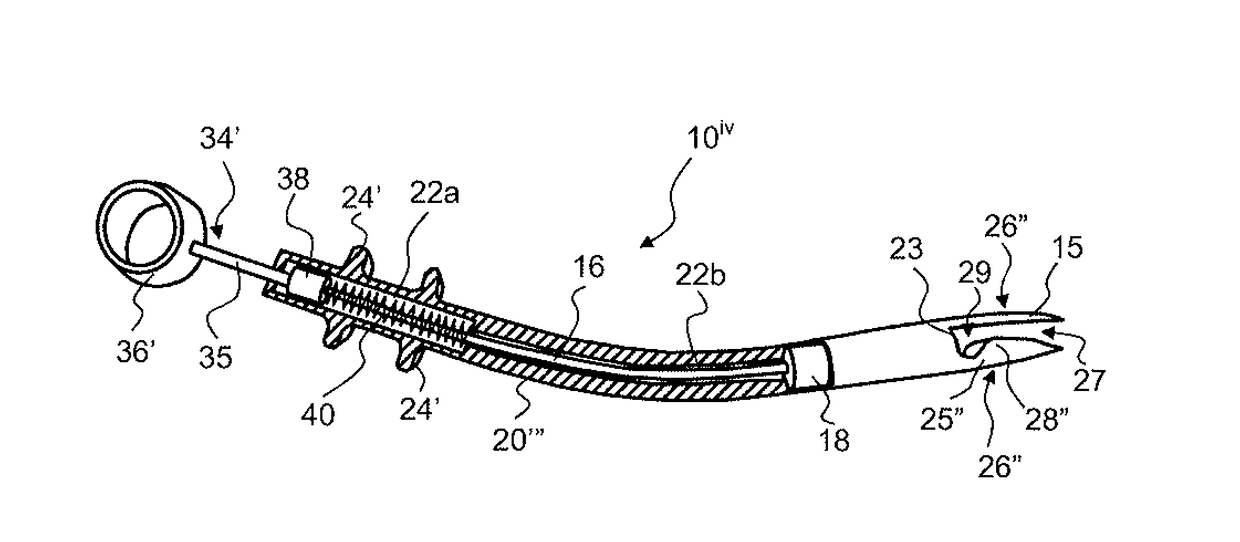
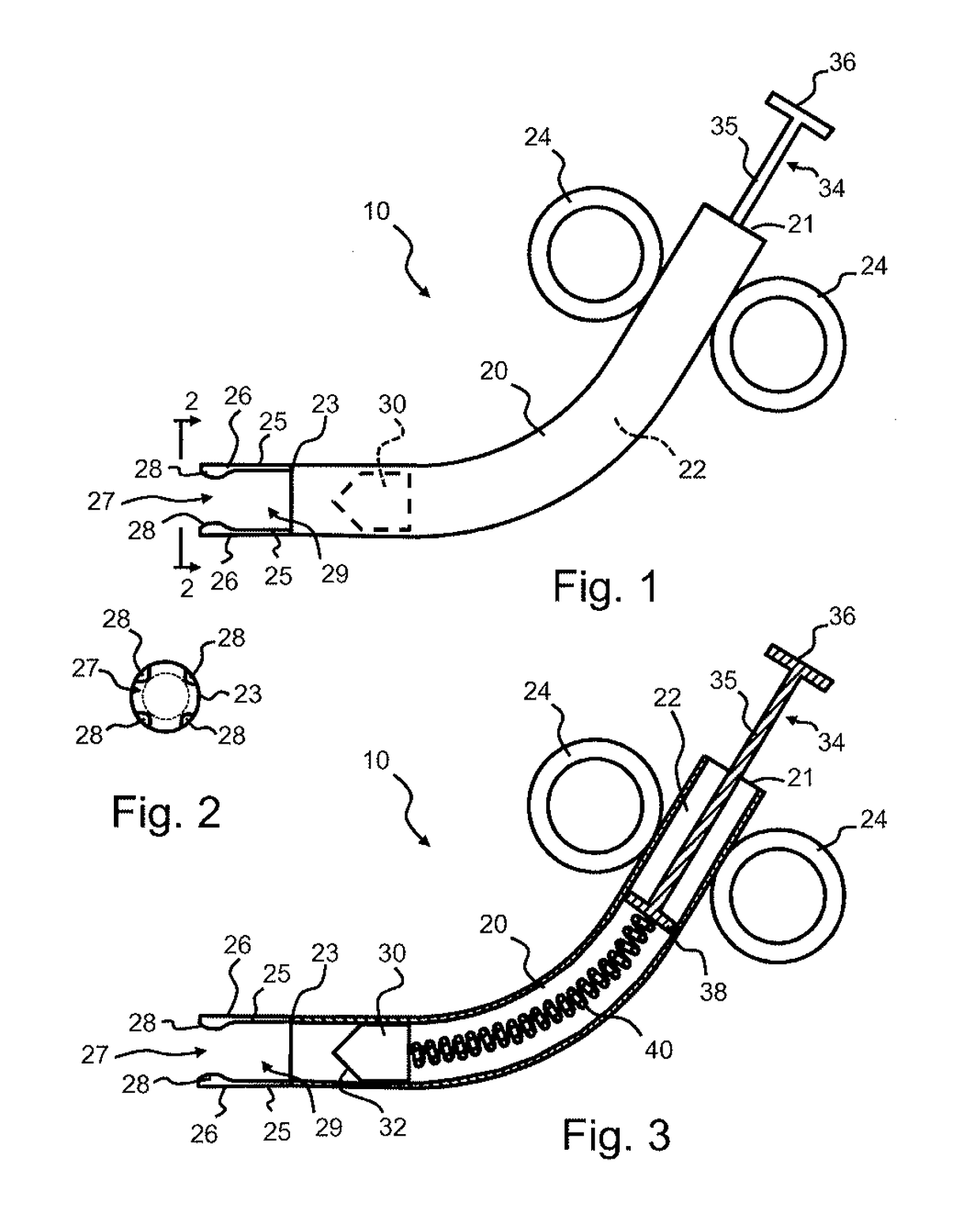
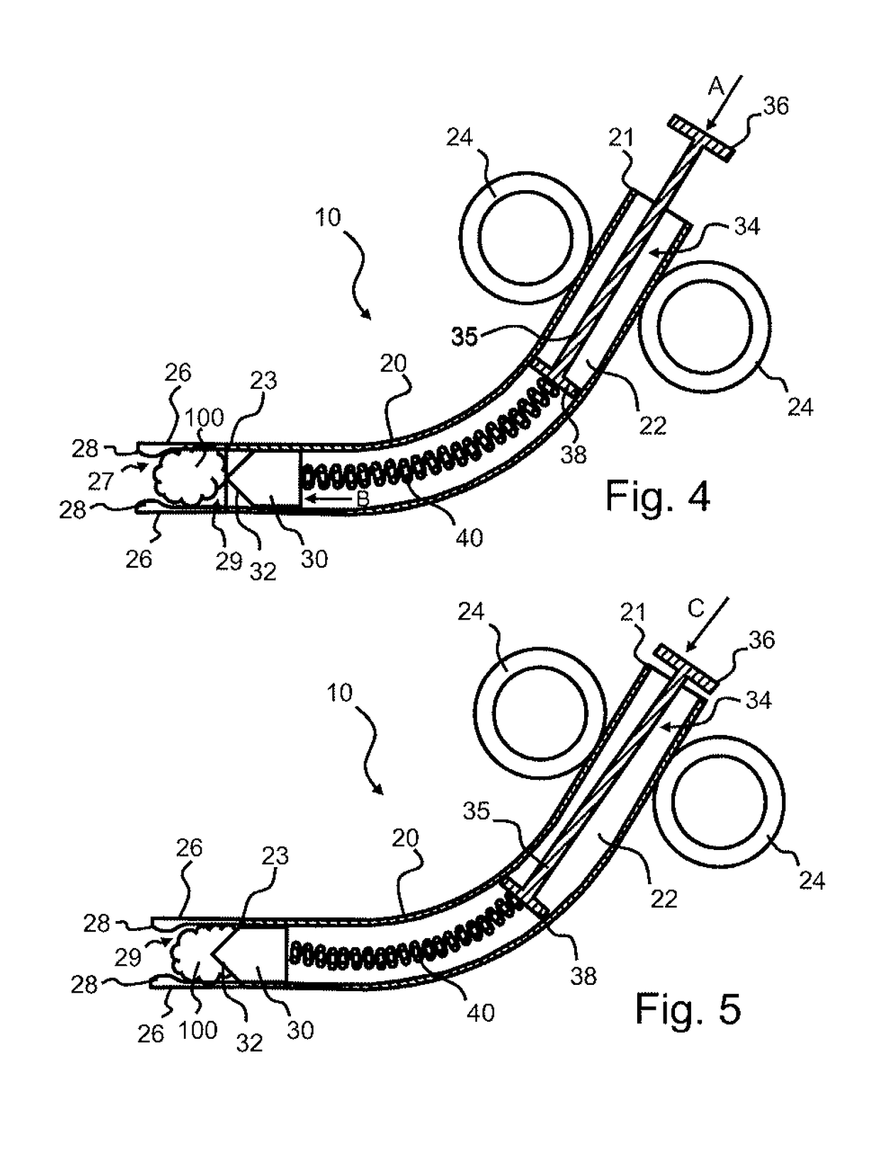
[0018]Referring to FIGS. 1-5, an exemplary transection device 10 in accordance with an embodiment of the invention will be described. The transection device 10 includes a tubular body 20 extending from an open proximal end 21 to an open distal end 23 with a hollow chamber 22 defined therebetween. While the ends 21, 23 are illustrated as opened, it is recognized that either end may be closed or sealed other than the passage of the plunger or blade as described hereinafter. In the illustrated embodiment, the body 20 has a curved configuration with the axis of the proximal end 21 angled a...


PUM


Abstract

A transection device including a hollow tubular body extending from a proximal end to a distal end. A plurality of stabilizing members extend from the distal end of the tubular body and define a reduced diameter opening into a receiving chamber adjacent the distal end of the tubular body. A blade is positioned within the tubular body and moveable between an initial position within the tubular body to an extended position wherein at least a portion of the blade extends into the receiving chamber. A depressible member extends from the proximal end and is configured to move the blade between the initial position and the extended position. A compression member may be positioned between the plunger member and the blade.

Description

[0001]This application claims the benefit of U.S. Provisional Application No. 62 / 073,337, filed on Oct. 31, 2014, the contents of which are incorporated herein by reference.FIELD OF THE INVENTION[0002]This present disclosure relates to a transection device. More particularly, the present disclosure relates to a transection device for tissue or vessels.BACKGROUND OF THE INVENTION[0003]In liver transplantation, there are two particularly challenging anastomoses: the hepatic artery and the bile duct. These structures are very delicate such that unnecessary and potentially excessive manipulation and handling may create tissue damage that may ultimately affect the functionality of the connections to the body. During the initial phase of operation (the hepatectomy phase) both structures must be ligated, only to be later transected again to create a smooth, regular, non-ischemic and defined surface for re-connection of these structures to those related structures of the donor organ. These ...

Claims


Application Information

Patent Timeline
Patent Type & Authority Applications(United States)
IPC IPC(8): A61B17/3209A61B17/00A61B17/11A61B17/32
CPCA61B17/3209A61B2017/00778A61B2017/320064A61B17/11A61B2017/1107A61B17/320016A61B2017/00862A61B2017/00969A61B90/03
Inventor WILSON, DORIAN J.
Owner RUTGERS THE STATE UNIV
Why Eureka
Try Eureka