
Shock Absorber with Gas Permeable Internal Floating Piston

a technology of internal floating piston and shock absorber, which is applied in the direction of shock absorbers, vibration dampers, springs/dampers, etc., can solve the problems of increasing manufacturing costs, complicating construction, and complicating construction, and achieve the effect of shortening the extended length

Inactive Publication Date: 2017-11-23
BANDY RONALD SCOTT
View PDF2 Cites 2 Cited by
  • Summary
  • Abstract
  • Description
  • Claims
  • Application Information

AI Technical Summary

Benefits of technology

The present invention is a single shock body or shock absorber that uses a gas permeable internal floating piston to separate oil from gas without additional manufacturing costs. This improves the dampening characteristics of the shock and enhances the separation of each stage in the air shock for improved performance. It also reduces the extended length of the air shock without affecting its spring rate.

Problems solved by technology

Charging of the shock during construction complicates the construction and increases the manufacturing costs.
This also complicates the construction and increases the manufacturing costs and requires an additional step to charge the shock with oil and gas.
In the case of air shocks, the increased work and costs prohibit internal floating pistons from being used.
The emulsion is well known in the art and is considered to provide unpredictable dampening properties in a shock absorber, which in turn, lead to unpredictable handling characteristics for the vehicle.
The deficiency of the emulsion lies in the mixing of the oil with the gas.
Such an addition process is not realistic for the multiple stage air shock.
However, one of the ends of one interconnecting component travels into another interconnecting component during the operation of the air shock, and therefore, is not available for receiving a check valve.

Method used


Image

  • Shock Absorber with Gas Permeable Internal Floating Piston
  • Shock Absorber with Gas Permeable Internal Floating Piston
  • Shock Absorber with Gas Permeable Internal Floating Piston

Examples


Embodiment Construction

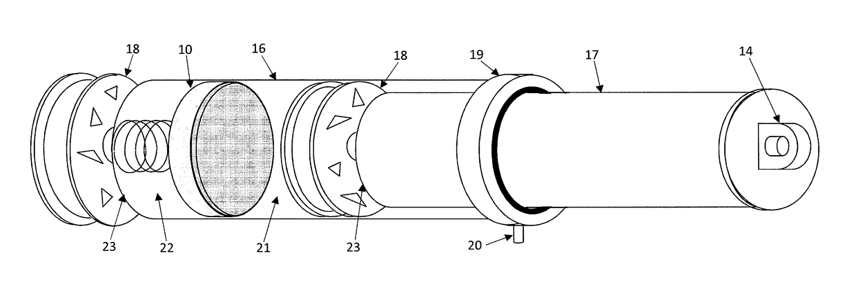
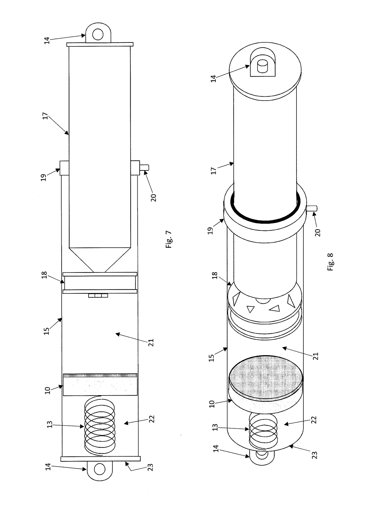
[0142]Detailed herein is the installation of the gas permeable internal floating piston in a single shock body, otherwise called a shock absorber or simply a shock. Emphasis is placed on the novel advantages of the gas permeable internal floating piston over an ordinary internal floating piston. Hereafter, the gas permeable internal floating piston can be called our gas permeable internal floating piston.

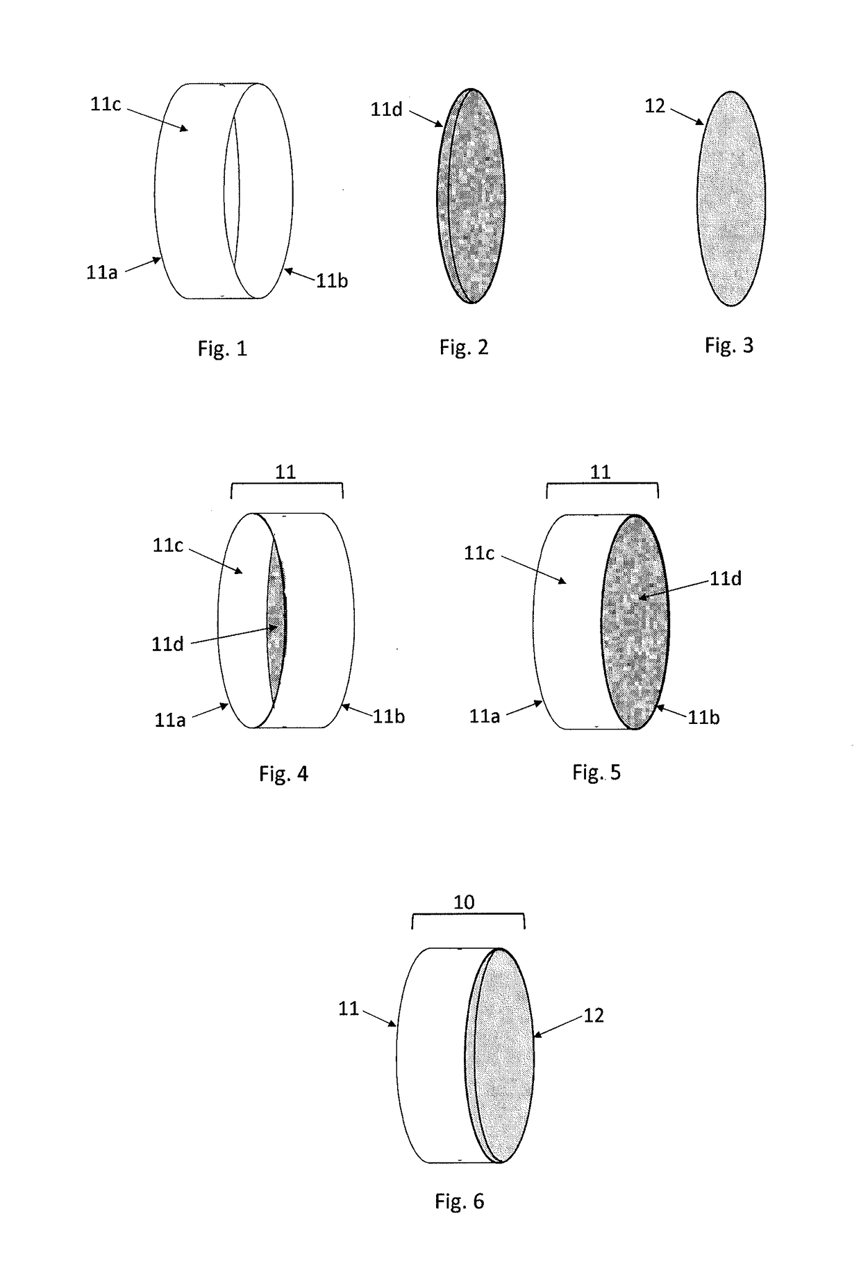
[0143]Our gas permeable internal floating piston comprises two components, a gas permeable membrane and an internal floating piston. Conversely, an ordinary internal floating piston comprises only one component, an internal floating piston. The ordinary internal floating piston lacks a gas permeable membrane or any other type of membrane. Therefore, the gas permeable membrane enables our gas permeable internal floating piston to separate the oil from the gas within the shock body while the ordinary internal floating piston cannot separate the oil from the gas at any location or time...


PUM


Abstract

Disclosed herein is a single shock body equipped with the gas permeable internal floating piston. The gas permeable internal floating piston was specifically designed for installation in the multiple stage air shock, the gas permeable internal floating piston being disclosed in the parent application. The gas permeable internal floating piston automatically separates the oil from the gas within the shock body thereby significantly reducing the complexity and cost of manufacturing a shock absorber with the gas permeable internal floating piston. Also, separation is maintained during the operation of the shock throughout the shock's lifetime. The gas permeable internal floating piston can operate with oils derived from either petroleum or synthetic base stocks, additives, and various gases including dry air, nitrogen, oxygen, carbon monoxide, carbon dioxide, helium, neon, and argon.

Description

CROSS-REFERENCE TO RELATED APPLICATIONS[0001]This application is a continuation-in-part of, and claims the benefit of priority to U.S. patent application Ser. No. 14 / 940,124, entitled “Gas Permeable Internal Floating Piston” filed on Nov. 12, 2015.STATEMENT REGARDING FEDERALLY SPONSORED RESEARCH OR DEVELOPMENT[0002]Not ApplicableREFERENCE TO SEQUENCE LISTING, A TABLE, OR A COMPUTER PROGRAM LISTING COMPACT DISC APPENDIX[0003]Not ApplicableBACKGROUND OF THE INVENTION[0004]The Internal floating piston (IFP) is commonly used to maintain separation of the oil from the gas during the operation of the shock absorber. The separation prevents the oil from mixing with the gas thereby significantly improving the dampening characteristics of the shock. Accordingly, the internal floating piston is a highly desirable component in a shock. In order for the internal floating piston to be effective, the internal floating piston must act as a permanent barrier and the oil and gas must be located on o...

Claims


Application Information

Patent Timeline
Patent Type & Authority Applications(United States)
IPC IPC(8): F16F9/06
CPCF16F9/061F16F9/067
Inventor BANDY, RONALD SCOTT
Owner BANDY RONALD SCOTT
Learn More