Power supply apparatus and power receiving apparatus

a power supply apparatus and power receiving technology, applied in the direction of instruments, liquid/fluent solid measurement, safety/protection circuit, etc., can solve the problems of increased cost of dc/dc converter, heat generation problem, and difficulty in such a conventional technique to detect abnormalities

Active Publication Date: 2017-11-23
ROHM CO LTD
View PDF5 Cites 16 Cited by
  • Summary
  • Abstract
  • Description
  • Claims
  • Application Information

AI Technical Summary

Benefits of technology

[0043]In this case, by monitoring, by means of the control circuit, the bus voltage on the bus line that is closer to the charger circuit side than the inductor, this allows the threshold voltage to be set without being affected by voltage fluctuation on the bus line due to the communication by the communication unit.
[0044]...

Problems solved by technology

This leads to a problem of increased costs required for the DC/DC converter 302.
However, in a case in which such a large amount of current flows through a chargin...

Method used


Image

  • Power supply apparatus and power receiving apparatus
  • Power supply apparatus and power receiving apparatus
  • Power supply apparatus and power receiving apparatus

Examples


first embodiment

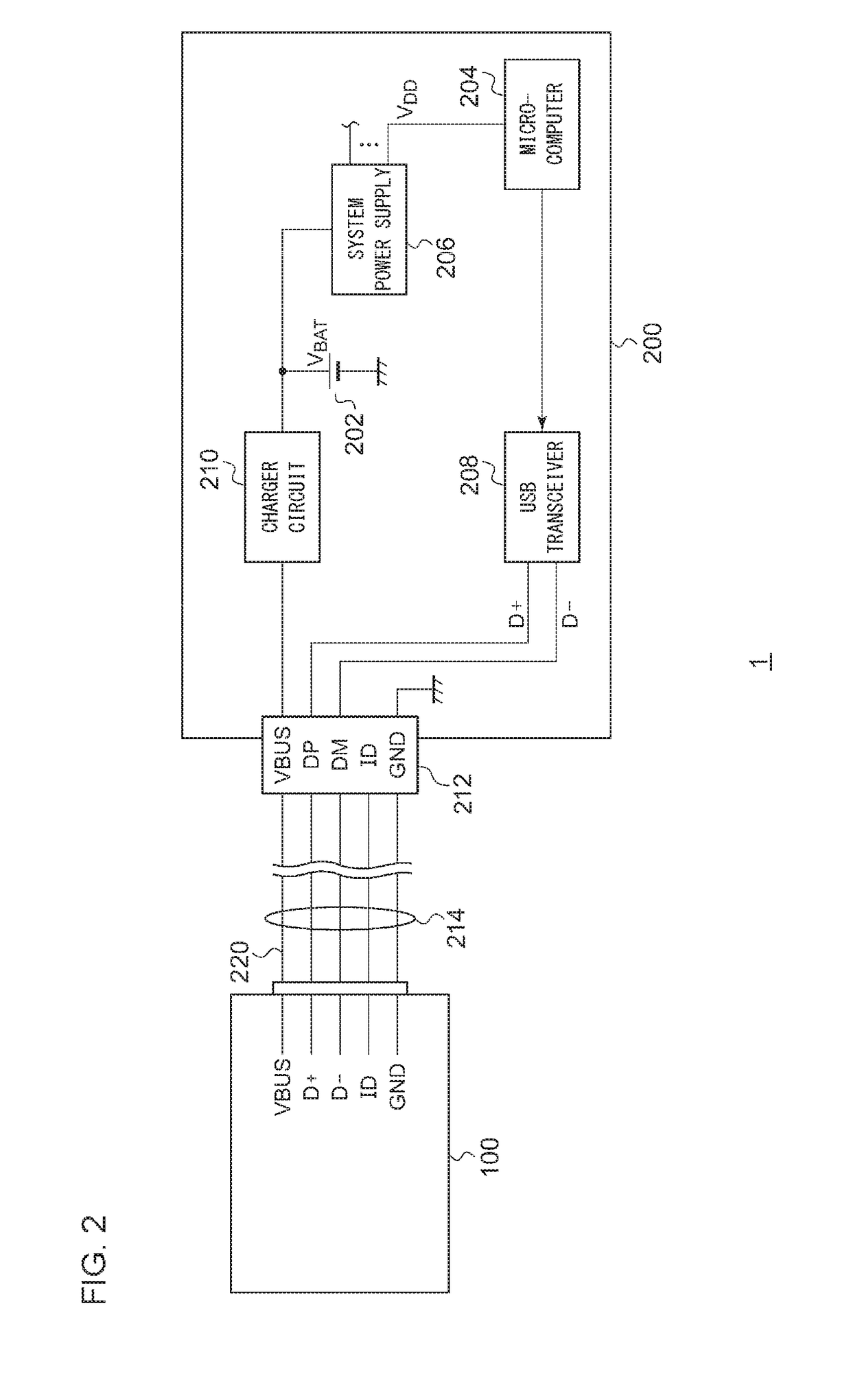
[0067]FIG. 2 is a block diagram showing a power supply system 1 including a power supply apparatus 100 according to a first embodiment. The power supply system 1 includes the power supply apparatus 100 and a power receiving apparatus 200. The power supply apparatus 100 and the power receiving apparatus 200 each supports USB-PD specification. The power receiving apparatus 200 is configured as a battery-driven information terminal device such as a cellular phone terminal, tablet terminal, laptop PC (Personal Computer), digital still camera, digital video camera, or the like.

[0068]The power receiving apparatus 200 includes a secondary battery 202, a microcomputer 204, a system power supply 206, a USB transceiver 208, and a charger circuit 210.

[0069]The secondary battery 202 is configured as a secondary battery such as a lithium-ion battery, a nickel hydride battery, or the like. The secondary battery 202 outputs the battery voltage VBAT. The number of cells employed in the secondary ba...

second embodiment

[0121]FIG. 6 is a block diagram showing a power supply system 1 including a power receiving apparatus 6 according to a second embodiment. The power supply system 1 includes a power supply apparatus 4 and the power receiving apparatus 6.

[0122]The power supply apparatus 4 and the power receiving apparatus 6 each supports USB-PD specification. The power receiving apparatus 6 is mounted on a battery-driven information terminal device such as a cellular phone terminal, tablet terminal, laptop PC (Personal Computer), digital still camera, digital video camera, or the like.

[0123]The power supply apparatus 4 and the power receiving apparatus 6 include connectors 40 and 60, respectively. The power supply apparatus 4 and the power receiving apparatus 6 are configured such that their connectors can be coupled via a USB cable 8. The power receiving apparatus 6 is configured to receive the supply of the bus voltage VBUS from the power supply apparatus 4, and to be capable of charging a built-in ...

first modification

[0155]Description has been made in the second embodiment regarding an arrangement in which the switch SW4 is configured with N-channel MOSFETs. However, the present invention is not restricted to such an arrangement. Also, P-channel MOSFETs may also be employed.


PUM


Abstract

A power supply apparatus supports USB-PD (Universal Serial Bus-Power Delivery) specification. A bus voltage VBUS is transmitted via a bus line. A first power supply circuit generates a first bus voltage having a first voltage level. A second power supply circuit generates a second bus voltage having a second voltage level that is higher than the first voltage level. A first switch is arranged between the bus line and an output terminal of the first power supply circuit. A second switch is arranged between the bus line and an output terminal of the second power supply circuit. A control circuit receives a control signal S1 via the bus line from a power receiving apparatus, which is a power supply target. The control circuit is structured to control the first switch and the second switch based on the control signal S1.

Description

CROSS REFERENCE TO RELATED APPLICATIONS[0001]The present application is a continuation of PCT / JP2016 / 050260, filed on Jan. 6, 2016 and claims priority under 35 U.S.C. §119 to Japanese Patent Applications No. 2015-012573, filed on Jan. 26, 2015 and No. 2015-012574, filed on Jan. 26, 2015, the entire contents of which are both incorporated herein by reference.BACKGROUND OF THE INVENTION1. Field of the Invention[0002]The present invention relates to a USB power supply.2. Description of the Related Art[0003]Battery-driven devices such as cellular phone terminals, tablet terminals, laptop personal computers, and portable audio players each include a rechargeable secondary battery and a charger circuit that charges the secondary battery as built-in components. A charger circuit is known, which charges a secondary battery using a DC voltage supplied from a USB (Universal Serial Bus) host adapter via a USB cable.[0004]At present, charger circuits mounted on mobile devices conform to a speci...

Claims


Application Information

Patent Timeline
IPC IPC(8): G06F1/26G06F1/20G06F1/32
CPCG06F1/266G06F1/3296G06F1/3287G06F1/20G06F1/26H02J1/082H02J7/00034H02J7/0029H02J7/00
Inventor KOGA, FUMINORI
Owner ROHM CO LTD
Why Eureka
Try Eureka