
Airway maintenance device

a maintenance device and airway technology, applied in the field of airway maintenance devices, can solve the problems of further limit the potential for vaping, the absence of the cuff, etc., and achieve the effects of increasing the sensitivity of the measurement, reducing or eliminating the effect of temperature on the pressure measurement, and increasing the sensitivity and robustness of the sensor

Active Publication Date: 2017-11-30
UNIVERSITY OF NOTTINGHAM
View PDF5 Cites 4 Cited by
  • Summary
  • Abstract
  • Description
  • Claims
  • Application Information

AI Technical Summary

Benefits of technology

The patent describes a device for maintaining the airway of a patient during intubation. The device includes a catheter with an inflatable cuff at its distal end. By monitoring the blood flow in the capillaries around the cuff, the device can adjust its pressure to reduce the risk of injury and promote better blood flow. The device can also adjust the pressure to prevent post-intubation stenosis, which can occur when the cuff is inflated for too long without being properly modulated. The pressure is adjusted based on the individual patient's needs and can be preset on the control unit. The control unit includes an optical pressure sensor that measures the pressure in the cuff and is connected to an inflation tube for controlling the pressure. This allows for continuous monitoring and adjustment of the pressure to promote better patient outcomes during intubation.

Problems solved by technology

In some circumstances, however, a cuff may be absent, for example for use in young children where the airway may be too narrow to accommodate a cuff without overly restricting the airway.
Lower volume cuffs are known to create a better seal than high volume cuffs, and with a reduced possibility of channels being created allowing the passage of fluids, and so further limit the potential for VAP.

Method used


Image

  • Airway maintenance device
  • Airway maintenance device
  • Airway maintenance device

Examples


Embodiment Construction

[0032]The invention is described in further detail below by way of example and with reference to the accompanying drawings, in which:

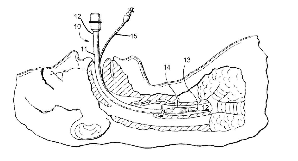
[0033]FIG. 1 is a schematic illustration of a conventional airway maintenance device in place within a patient;

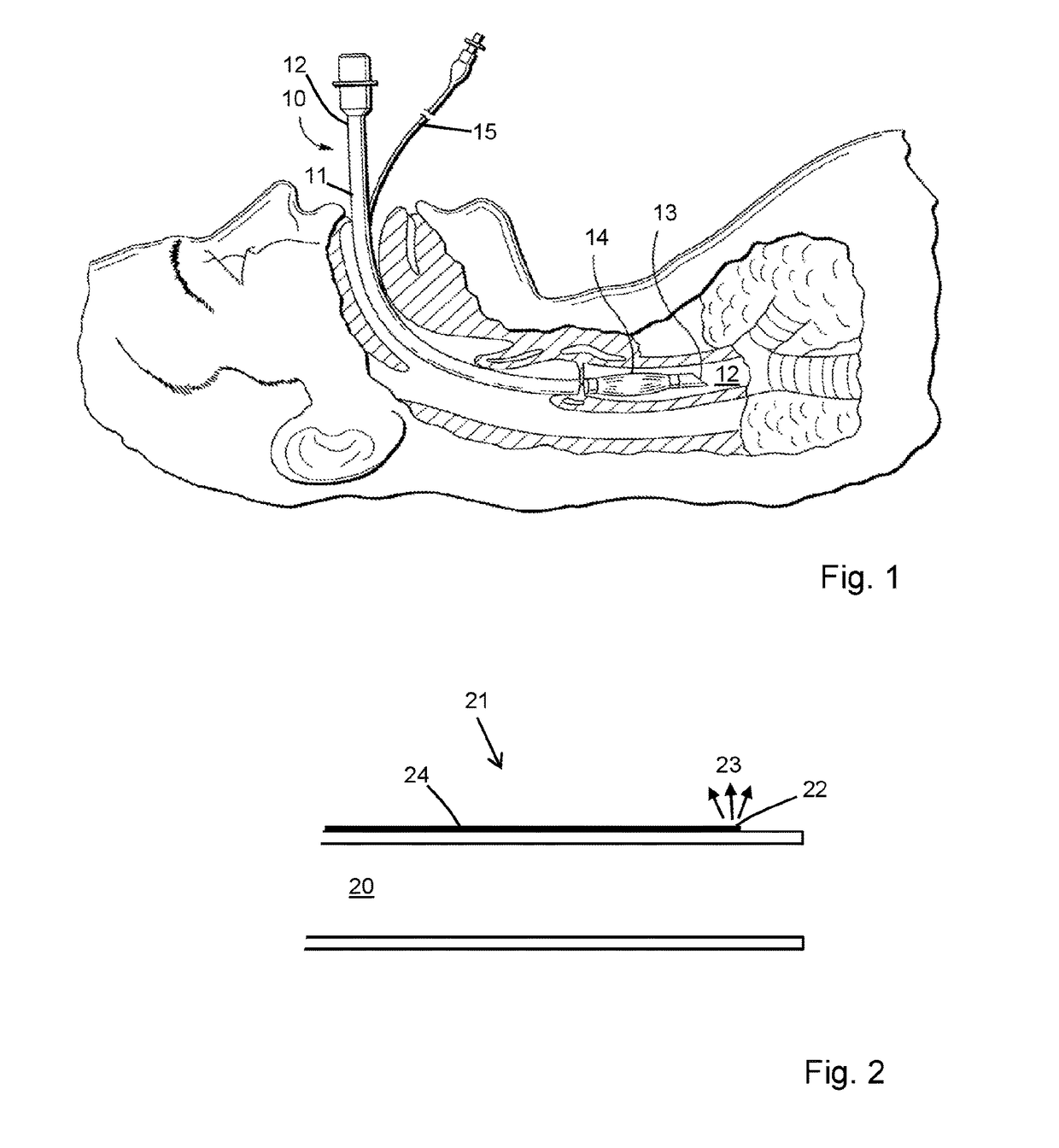
[0034]FIG. 2 is a schematic diagram of a distal end portion of an exemplary airway maintenance device;

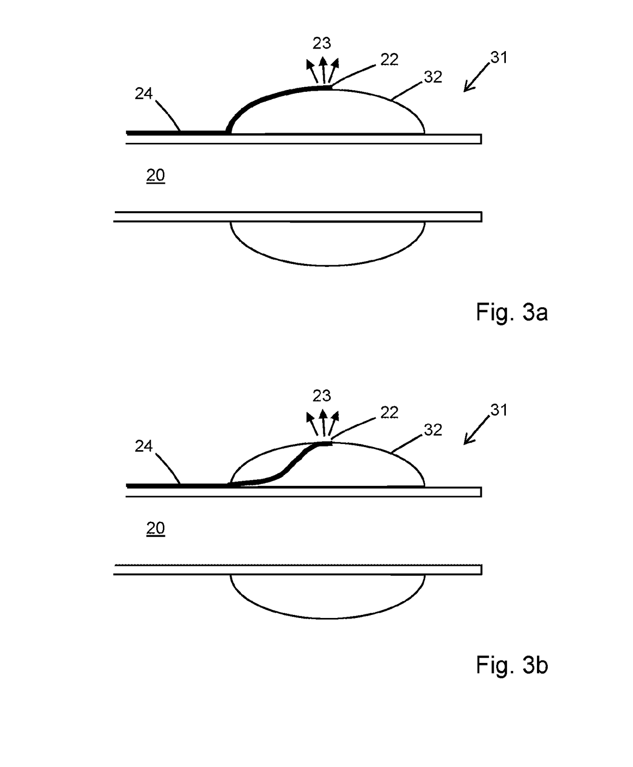
[0035]FIG. 3a a schematic diagram of a distal end portion of an alternative exemplary airway maintenance device;

[0036]FIG. 3b is a schematic diagram of a distal end portion of a further alternative exemplary airway maintenance device;

[0037]FIG. 4a is a schematic diagram of an optical sensor arrangement;

[0038]FIG. 4b is a schematic diagram of an alternative optical sensor arrangement;

[0039]FIG. 4c is a schematic diagram of a further alternative optical sensor arrangement;

[0040]FIG. 4d is a schematic diagram of a further alternative optical sensor arrangement;

[0041]FIG. 5 is a schematic cross-sectional view of a distal end portion of an airway m...


PUM


Abstract

The disclosure relates to an airway maintenance device, such as an endotracheal tube, tracheostomy tube, or supraglottic airway device, and in particular to an airway maintenance device having a sensor for measuring capillary blood flow and / or pressure. The device includes an airway maintenance device with an airway lumen having a proximal end and a distal end, a distal end portion incorporating an optical sensor configured to measure capillary blood flow in tissue surrounding the distal end when in position within a patient's airway. The optical sensor may include a portion of an optical fibre extending to the distal end portion along the lumen.

Description

FIELD OF THE INVENTION[0001]The invention relates to an airway maintenance device, such as an endotracheal tube, tracheostomy tube, or supraglottic airway device, and in particular to an airway maintenance device having a sensor for measuring capillary blood flow and / or pressure.BACKGROUND[0002]Airway maintenance devices, such as endotracheal tubes, are integral to critical patient care. Such devices will often include an inflatable cuff to provide a gas seal within the surrounding airway, which, by reducing leakage of gas around the cuff, facilitates mechanical ventilation of the lungs. Forming a reliable fluid seal between the cuff and the airway is also important for preventing flow of infected secretions travelling from the mouth, past the cuff, and into the lungs.[0003]Pressure exerted by an inflatable cuff on the airway wall can in some cases cause ulceration and scarring of the airway. This problem can be compounded by over-inflation of the cuff by medical practitioners. It i...

Claims


Application Information

Patent Timeline
IPC IPC(8): A61B5/026A61M16/04A61B5/0205A61B5/00
CPCA61B5/0261A61M16/0434A61M16/0402A61M2205/3334A61B5/6885A61M16/0409A61M2205/3306A61B5/02055A61M16/04A61M16/044A61M16/0465A61M16/0456A61M2205/3368
Inventor MORGAN, STEPHEN P.HAYES-GILL, BARRIE R.KORPOSH, SERGIYCORREIA, RICARDOHARDMAN, JONATHANNORRIS, ANDREW
Owner UNIVERSITY OF NOTTINGHAM
Learn More