
Method of manufacturing a component of a rotary machine and component manufactured using said method

a manufacturing method and rotary machine technology, applied in the direction of manufacturing tools, liquid fuel engines, turbines, etc., can solve the problems of high load or criticality, inability to manufacture total cutting parts in many cases, and the border region between the blades and the top plate is particularly prone to joining defects, etc., to achieve fast and problem-free change, high precision and surface quality of components, and high quality. the effect of quality

Active Publication Date: 2017-11-30
SULZER MANAGEMENT AG
View PDF3 Cites 4 Cited by
  • Summary
  • Abstract
  • Description
  • Claims
  • Application Information

AI Technical Summary

Benefits of technology

The patent text describes a method for manufacturing components using a combination of additive and subtractive machining processes. The technical effects include the use of forged materials that are then machined to maintain their advantages, the manufacturing of openings in the component that are exposed to high loads in the operating state, and the ability to change between subtractive and additive machining processes quickly and efficiently. This method allows for the production of components with high load capacity, reliability, and precision. Additionally, the use of machining apparatus that allow for the combination of additive and subtractive machining processes further enhances the speed, cost-effectiveness, and quality of the manufacturing process.

Problems solved by technology

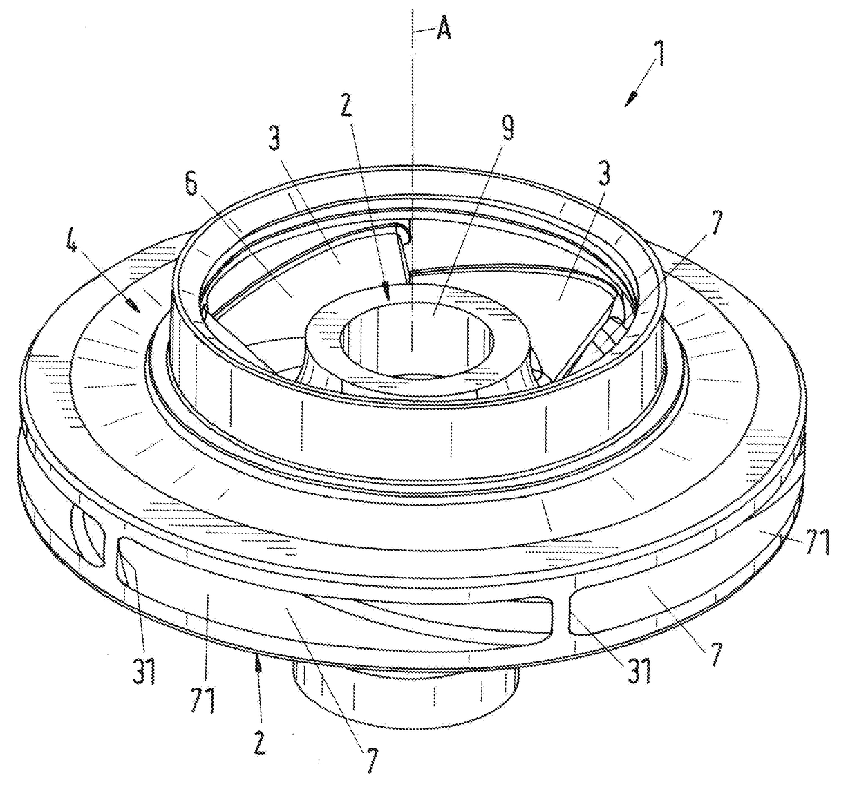
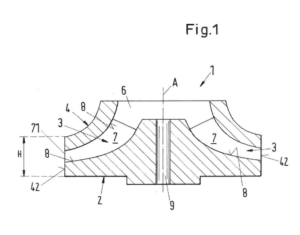
Even if it is considered that these passages can be milled or machined from the blank in a cutting process from both sides, that is from the inner space of the impeller and from its radial boundary surface, using a cutting apparatus, it is clear that the geometry sets limits here and makes a total cutting manufacture impossible in many cases.
However, this brings about the disadvantage that the loads are particularly high or critical at just this point in the operating state.
This border region between the blades and the top plate is particularly prone to joining defects that are sometimes not even noticed during the manufacture.
These methods are, however, comparatively slow and cost-intensive as a rule.
A cast component has the disadvantage, however, that defects in the structural conditions may occur during molding, for example, that have a negative effect on the load capacity or on the stability of the component.
As a rule, the achievable surface qualities and the dimensional accuracies of the regions no longer accessible to milling are furthermore limited in the molding process.
This method is, however, also still subject to geometrically caused limits.
This problem explained with reference to closed impellers is, however, also present with other components that have an inner passage whose position or geometry is such that a total cutting manufacture is in particular not possible or not practical for geometrical reasons.
However, this does not mean that the passage is thereby completed.

Method used


Image

  • Method of manufacturing a component of a rotary machine and component manufactured using said method
  • Method of manufacturing a component of a rotary machine and component manufactured using said method
  • Method of manufacturing a component of a rotary machine and component manufactured using said method

Examples


Embodiment Construction

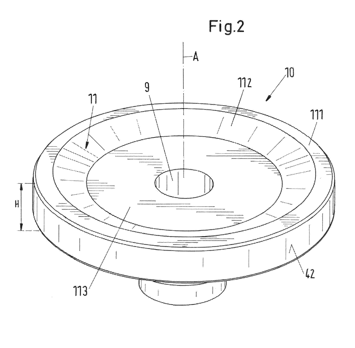
[0042]The method in accordance with the invention serves for the manufacture of a component of a rotary machine, wherein the component has at least one inner passage that extends from a center up to a boundary surface of the component and is at least partly closed. In this respect, a closed passage means a passage that is completely closed with the exception of an inlet or of an outlet, that is, is configured as tubular, that is the passage is bounded everywhere by one or more walls perpendicular to its main direction of flow. Unlike this, an open passage means one that is not bounded by a wall, but is open, in a direction perpendicular to its main direction of flow, that is in a direction perpendicular to its longitudinal extent. A passage having a U-shaped or V-shaped wall is thus an open passage, for example. If the open side of the U section or of the V section were to be covered by a top, the passage would be a closed passage.

[0043]A partly closed passage then means one that is...


PUM

PropertyMeasurementUnit
shapeaaaaaaaaaa
strengthaaaaaaaaaa
stabilityaaaaaaaaaa

Abstract

A method of manufacturing a component of a rotary machine, the component has at least one inner passage that extends from a center up to a boundary surface of the component and is at least partly closed, and a blank is provided that includes the boundary surface and a top surface. The Method includes a first subtractive machining step that is carried out in which a part of the passage that at least includes an opening of the passage into the boundary surface as well as a cut-out in the top surface are manufactured by machining production, and subsequently the passage is completed by build-up production on the blank.

Description

CROSS-REFERENCE TO RELATED APPLICATION[0001]This application claims priority to European Application No. 16172289.7, filed May 31, 2016, the contents of which are hereby incorporated herein by reference.BACKGROUNDField of the Invention[0002]The invention relates to a method of manufacturing a component of a rotary machine and to a component of a rotary machine.Background of the Invention[0003]In the manufacture of rotary machines such as pumps, turbines, compressors, compactors or expanders, it is known to work rotating rotors, pump wheels, impellers and stationary diffusers or guide wheels as components out of blanks by cutting or machining processes, for example by milling. In this respect, the blank can be present as solid material or can already be pre-worked by a primary shaping process.[0004]Such a method is known, for example, from EP-B-2 012 957. The method proposed there is in particular characterized in that it allows a cutting manufacture of the component, by which it is ...

Claims


Application Information

Patent Timeline
Patent Type & Authority Applications(United States)
IPC IPC(8): B23K26/00B33Y80/00B23K26/342B23K9/04B23K9/167B33Y10/00B33Y40/00B23K10/02B23K101/00F01D5/04F01D9/04F04D29/22F04D29/28F04D29/44
CPCB23K26/0093F05D2230/50B23K9/167B23K10/027B23K26/342B33Y10/00B33Y40/00B33Y80/00B23K2201/001F01D5/04F01D9/041F04D29/22F04D29/448F04D29/444F04D29/284F05D2230/10B23K9/044B23C3/18B23P15/00B23P15/02B23P15/006F04D29/2227F05D2230/22F05D2230/31B23K2101/001B23P13/02B23P23/04F02B39/00F01D5/12F01D5/34F03B3/12F04D29/28F05D2230/53
Inventor RETTBERG, ROBINKRANZLER, THOMASWURMS, ANDREAS
Owner SULZER MANAGEMENT AG
Learn More