
Viscoelastic liquid-cooled actuator

a liquid-cooled actuator, viscoelastic technology, applied in the direction of gearing, force/torque/work measurement apparatus, instruments, etc., can solve the problems of limiting the system performance and the scope of possible applications, poor efficiency, and under average performance in other directions

Inactive Publication Date: 2017-11-30
BOARD OF RGT THE UNIV OF TEXAS SYST
View PDF0 Cites 20 Cited by
  • Summary
  • Abstract
  • Description
  • Claims
  • Application Information

AI Technical Summary

Benefits of technology

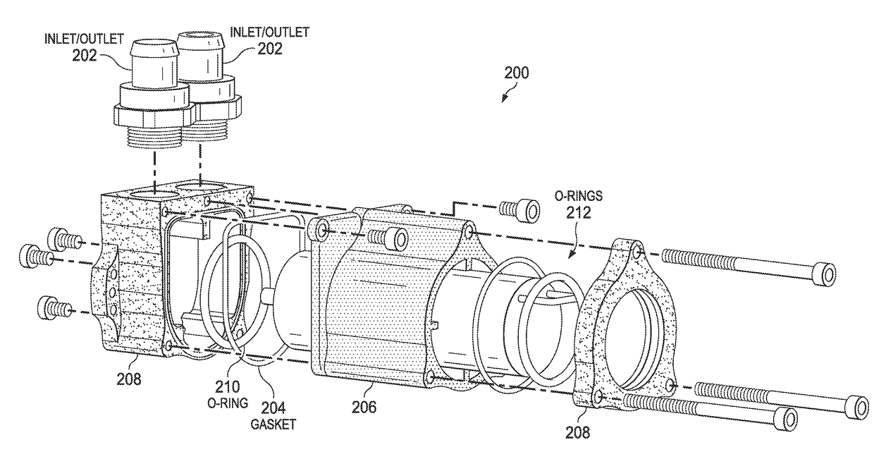
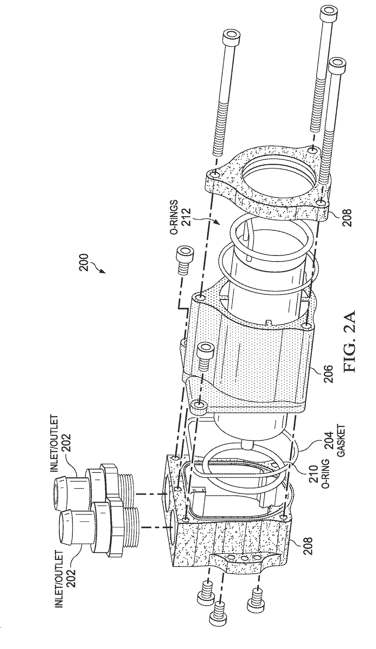
The patent text describes a system and method for creating robotic actuators that use a viscoelastic liquid-cooled actuator and a speed reduction element to amplify motor torque. The viscoelastic material is placed in series with the load path of the actuator and can measure force through an encoder. The actuator can also include a series elastic actuator and a liquid-cooled motor enclosed in a removable fluid seal. The system and method can be used to create robotic actuators with improved performance and control.

Problems solved by technology

Actuators that are overly heavy or bulky strain the other elements of the system in which they function, and limit the performance of the system and the scope of possible applications.
For example, hydraulic actuators exhibit above average power density, impact tolerance, position controllability and force controllability, but poor efficiency.
Pneumatic actuators exhibit relatively good impact tolerance, but below average performance in other areas.
Geared electric (air-cooled) actuators exhibit good efficiency and position controllability, but poor power density, impact tolerance, and force controllability.
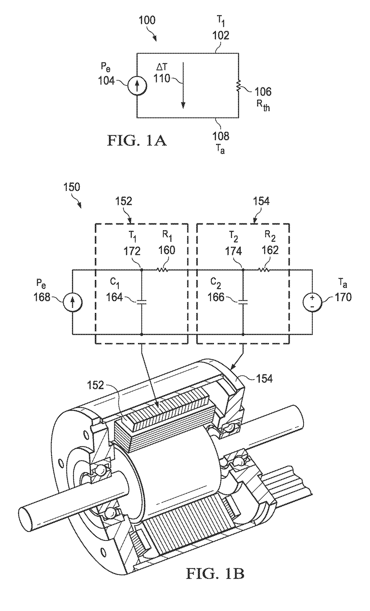
Liquid-cooled electric motors are typically reserved for large, expensive, high-end applications where the design of the motor's electromagnetic components are closely coupled to its cooling system.
Because these motors are typically custom made, they can be very expensive and require a long development time.
However, this type of motor is rarely designed for use with liquid cooling

Method used


Image

  • Viscoelastic liquid-cooled actuator
  • Viscoelastic liquid-cooled actuator
  • Viscoelastic liquid-cooled actuator

Examples


example instrumentation

and Dynamometry

[0079]In some embodiments of the present disclosure, a controllable motor load and a large suite of sensors may be used to enable thermal control and to fully characterize motor performance. For example, FIGS. 4 and 5 illustrate components of a system for characterizing motor performance, according to at least some embodiments. More specifically, FIG. 4 illustrates an example motor test bed, according to one embodiment. This illustration shows the test bed as configured for liquid cooling. For the air cooling tests described herein, a bare motor was used. This system is interfaced to a microcontroller, as described below. In this example, test bed 400 includes a radiator 402, a pulley drivetrain 404, belt tensioners 406, a reaction torque sensor 408, a shaft coupler 410, a fluid reservoir 412, a hysteresis brake 414 , a liquid-cooled servo drive 416 (which may be the same as or similar to the liquid-cooled motor driver illustrated in FIGS. 3A and 3B), a centrifugal pu...


PUM


Abstract

A robotic actuator may include a series elastic actuator (SEA) that includes an elastic element made of a viscoelastic material. The viscoelastic material may have hardness, stiffness, hysteresis, or damping properties suitable for a particular robotic application. The elastic element may include two portions of the viscoelastic material in compression with each other in the SEA. The SEA may include a motor to generate mechanical power, a speed reduction element to amplify motor torque, an encoder to measure deflection of the viscoelastic elastomer due to an applied force, and a transmission mechanism. The transmission mechanism may be connected to the motor using a pulley and may route mechanical power to an output joint. The SEA may be a prismatic SEA or another type of linear actuator. The motor may include a 3D printed liquid cooling jacket that includes removable fluid seals and that is assembled and disassembled using removable screws.

Description

CROSS-REFERENCE TO RELATED APPLICATIONS[0001]This application claims priority from U.S. Provisional Application No. 62 / 340,885, filed May 24, 2016, entitled “VISCOELASTIC LIQUID-COOLED ACTUATOR” the contents of which is incorporated herein by reference.STATEMENT OF GOVERNMENT SUPPORT[0002]This invention was made with government support under Grant no. NNX12AQ99G awarded by the National Aeronautics and Space Administration. The government has certain rights in the invention.FIELD OF THE DISCLOSURE[0003]The present disclosure relates generally to the field of robotic actuators and, more particularly, to robotic actuators that include viscoelastic elements and liquid-cooled motors.DESCRIPTION OF THE RELATED ART[0004]Actuation for robotic applications is best provided by an actuator that is light-weight, and compact, with an ability to generate high power and force, yet efficient in its operation. Such applications typically require that the actuator is capable of precise force control ...

Claims


Application Information

Patent Timeline
IPC IPC(8): B25J9/12H02K5/24G01L5/00H02K11/24H02K9/197B25J13/08B25J9/10G01L1/04F16H25/20F16H25/22
CPCB25J9/123G01L1/04G01L5/0061B25J13/085F16H2025/2096H02K5/24H02K11/24H02K9/197F16H25/22B25J9/104H02K7/06B25J19/0054B25J19/0091F16H25/2204H02K5/203
Inventor SENTIS, LUISPAINE, NICHOLAS
Owner BOARD OF RGT THE UNIV OF TEXAS SYST
Learn More