Range extension for optical fiber sensing systems

a technology of optical fiber and sensing pulses, applied in the field of optical fiber sensing systems, can solve the problems of increasing the system deployment cost, the range of most optical fiber das and dts systems is limited to around 5 km, etc., and achieves the effects of increasing the range, increasing the power of any sensing pulse, and increasing the power of backscatter

Active Publication Date: 2017-11-30
SILIXA +1
View PDF9 Cites 22 Cited by
  • Summary
  • Abstract
  • Description
  • Claims
  • Application Information

AI Technical Summary

Benefits of technology

[0006]In order to address the above problem the present invention applies techniques known already from the telecommunications industry, and in particular the provision of repeater amplifiers such as erbium doped fiber amplifiers (EDFAs), to provide for an optical fiber sensor of increased range. In particular, in an optical fiber sensing system of embodiments of the present invention one or more optical amplifiers, such as optical fiber amplifiers like EDFAs, are provided in series with the sensing fiber in order to increase the power of any sensing pulses being sent in a forward direction along the fiber. Optical circulators are provided either side of the optical amplifier, to allow backscattered and/or reflected light to be routed around the forward path optical amplifier. In some embodiments an optical amplifier may also be provided in the backscatter and/or reflections feedback path, to increase the power of

Problems solved by technology

At present most optical fiber DAS and DTS systems are limited in range to around 5 km or so, due to attenuation in the fiber of both of the outward sensing pulse, and the resulting backscatter and/or reflections along the fiber.
Whilst range can of course be increased by the pr

Method used


Image

  • Range extension for optical fiber sensing systems
  • Range extension for optical fiber sensing systems
  • Range extension for optical fiber sensing systems

Examples


first embodiment

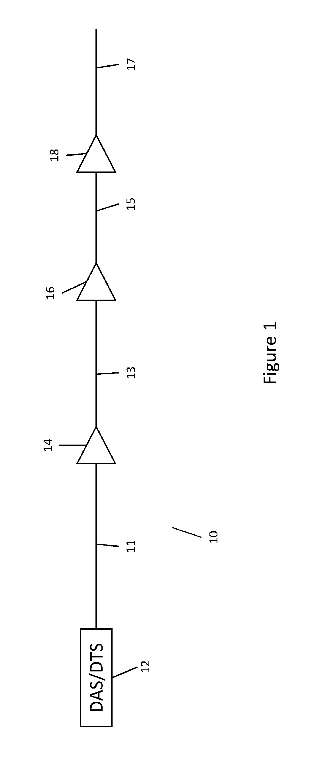
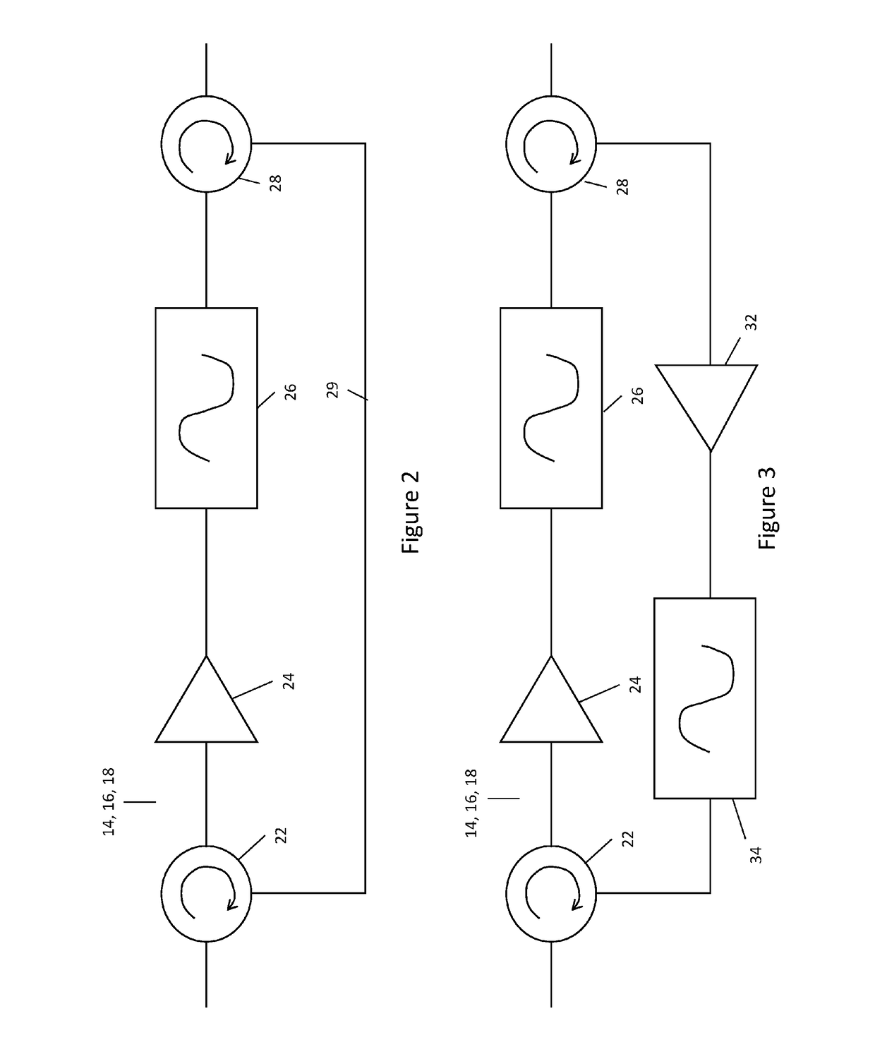
[0026]FIG. 2 illustrates the optical amplifier modules 14, 16, or 18. In the forward path the amplifier module 14, 16, 18 comprises a first circulator 22, which is a three port device where a signal input at a first port is output at a second port, whereas a signal input at the second port is output at the third port. Correspondingly, a signal input at the third port is output at the first port. Optical circulators are of course known in the art, and no further description of the internal operation thereof will be undertaken. The first port of the optical circulator 22 receives is connected to the optical fiber 11, 13, or 15 of the preceding fiber length, whereas the second port of the optical circulator is connected via an optical fiber to the input of an optical amplifier 24, such as an optical fiber amplifier like an erbium doped fiber 8mplifier (EDFA). The optical amplifier 24 acts to amplify the power of the incoming pulses received from the optical circulator, and then feeds t...

third embodiment

[0031]One advantage of the arrangement of the third embodiment is that the forward pulse is effectively regenerated for each subsequent length of sensing fiber. Not only does this provide for improved pulse quality along any particular length of sensing fiber, but it also allows for different wave lengths of pulse to be used for the different lengths of sensing fiber. For example, therefore, a different wavelength of forward pulse could be used for sensing fiber 11 compared to sensing fiber 13, as well as for sensing fiber length 15, and for sensing fiber length 17. This helps with signal discrimination in the sensor source apparatus, as the backscatter and / or reflections from a particular length of sensing fiber will be of the same wavelength as the forward pulse on that sensing fiber. Hence, effectively, in this embodiment up to four different wavelengths of backscatter and / or reflections will propagate back down the fiber, and which can then be detected at the sensor source appar...


PUM


Abstract

An optical fiber sensing system includes a sensing optical fiber and one or more optical amplifiers in series with the sensing fiber and arranged to increase the power of sensing pulses travelling along the fiber to thereby increase the range of the sensing system. The optical fiber sensing system is one selected from the group including an optical fiber distributed acoustic sensor (DAS), an optical fiber distributed temperature sensor (DTS), or an optical time domain reflectometry (OTDR) system.

Description

TECHNICAL FIELD[0001]The present invention relates to optical fiber sensing systems, such as optical time domain reflectometers (OTDRs), as well as optical fiber distributed acoustic sensors (DASs), and optical fiber distributed temperature sensors (DTSs). Specifically, the present invention provides for range extension of such sensing systems by providing for optical signal repeater or amplifier modules to increase the power of any sensing pulses sent down the optical fiber.BACKGROUND TO THE INVENTION AND PRIOR ART[0002]Optical fiber based sensing systems are known already in the art. OTDRs are used to determine fiber condition and properties, such as splice or connector losses and attenuation, whereas DAS and DTS systems use backscatter and / or reflections from along the fiber to sense acoustic energy incident on the fiber, or ambient temperature around the fiber, as appropriate. An example prior art DAS system is the Silixa® iDAS™ system, available from Silixa Ltd, of Elstree, UK,...

Claims


Application Information

Patent Timeline
IPC IPC(8): G01D5/353G01H9/00G01K11/32G01M11/00
CPCG01D5/35358G01M11/3109G01K11/32G01H9/004G01D5/353G01D5/35338G01D5/35354
Inventor PARKER, TOMFARHADIROUSHAN, MAHMOUDGILLIES, ARRAN
Owner SILIXA
Why Eureka
Try Eureka