

Organic el device, method for manufacturing organic el device, and electronic instrument
- Summary
- Abstract
- Description
- Claims
- Application Information
AI Technical Summary
Benefits of technology
Problems solved by technology
Method used
Image

Examples
example 1
[0086]FIG. 7A is a cross-sectional view of an electrooptical device 1 of Example 1. FIG. 7B is a view schematically illustrating a material used for each layer of the electrooptical device 1 of Example 1 and the layer thickness of each layer.
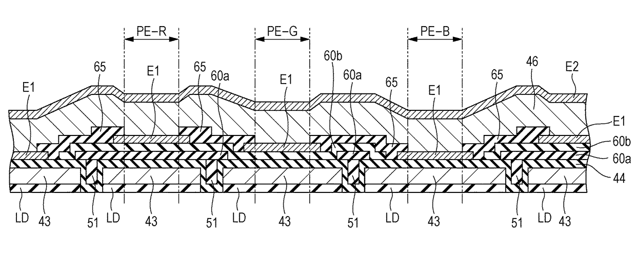
[0087]As illustrated in FIG. 7A, the electrooptical device 1 according to Example 1 is different from the electrooptical device 1 of the embodiment illustrated in FIG. 4 in that a third optical path length adjusting layer 60c was formed. In Example 1, a first optical path length adjusting layer 60a3, a second optical path length adjusting layer 60b3, and the third optical path length adjusting layer 60c3 are laminated on an protective layer 44-3 in the subpixel PE-R and optical path adjustment is performed by the first optical path length adjusting layer 60a3, the second optical path length adjusting layer 60b3, and the third optical path length adjusting layer 60c3. In the subpixel PE-G, the second optical path length adjusting layer 60b3 and t...
example 2
[0089]FIG. 8 is a view schematically illustrating a material used for each layer of the electrooptical device 1 of Example 2 and the layer thickness of each layer. Example 2 is the same as Example 1 in that silicon oxide (SiO2) was used as a protective layer 44-4. Also in Example 2, the protective layer 44-4 is in contact with the reflective layer 43 and also functions as a reflection enhancing layer. However, the protective layer 44-4 is different from that of Example 1 in that the layer thickness was set to 111 nm. When the layer thickness of the silicon oxide (SiO2) as the protective layer 44-4 is small, there is a risk in terms of a process. Therefore, in order to avoid the risk, the layer thickness is made thick in Example 2. Moreover, Example 2 is different from Example 1 in that, in order to increase the layer thickness of the silicon oxide (SiO2) as the protective layer 44-4, no optical path length adjusting layer is provided in the subpixel PE-B. More specifically, the opti...
example 3
[0093]FIG. 9 is a view schematically illustrating a material used for each layer of an electrooptical device 1 of Example 3 and the layer thickness of each layer. Example 3 is different from Example 2 in that the first optical path length adjusting layer 60a5 and the second optical path length adjusting layer 60b5 were formed of tantalum oxide (Ta2O5). In Example 3, the “optical path length adjusting layer” in Claims is a general term for a first optical path length adjusting layer 60a5 and a second optical path length adjusting layer 60b5.
[0094]In Example 3, in the subpixel PE-R, the first optical path length adjusting layer 60a5 and the second optical path length adjusting layer 60b5 are laminated on the protective layer 44-4 and optical path adjustment is performed by the first optical path length adjusting layer 60a5 and the second optical path length adjusting layer 60b5. In the subpixel PE-G, the second optical path length adjusting layer 60b5 is formed on the protective layer...
PUM
 Abstract
Description
Claims
Application Information