System and method for a dc/dc converter

Active Publication Date: 2017-12-07
GENERAL ELECTRIC CO
View PDF5 Cites 17 Cited by
  • Summary
  • Abstract
  • Description
  • Claims
  • Application Information

AI Technical Summary

Problems solved by technology

In this topology, all of the power is processed b

Method used


Image

  • System and method for a dc/dc converter
  • System and method for a dc/dc converter
  • System and method for a dc/dc converter

Examples


Embodiment Construction

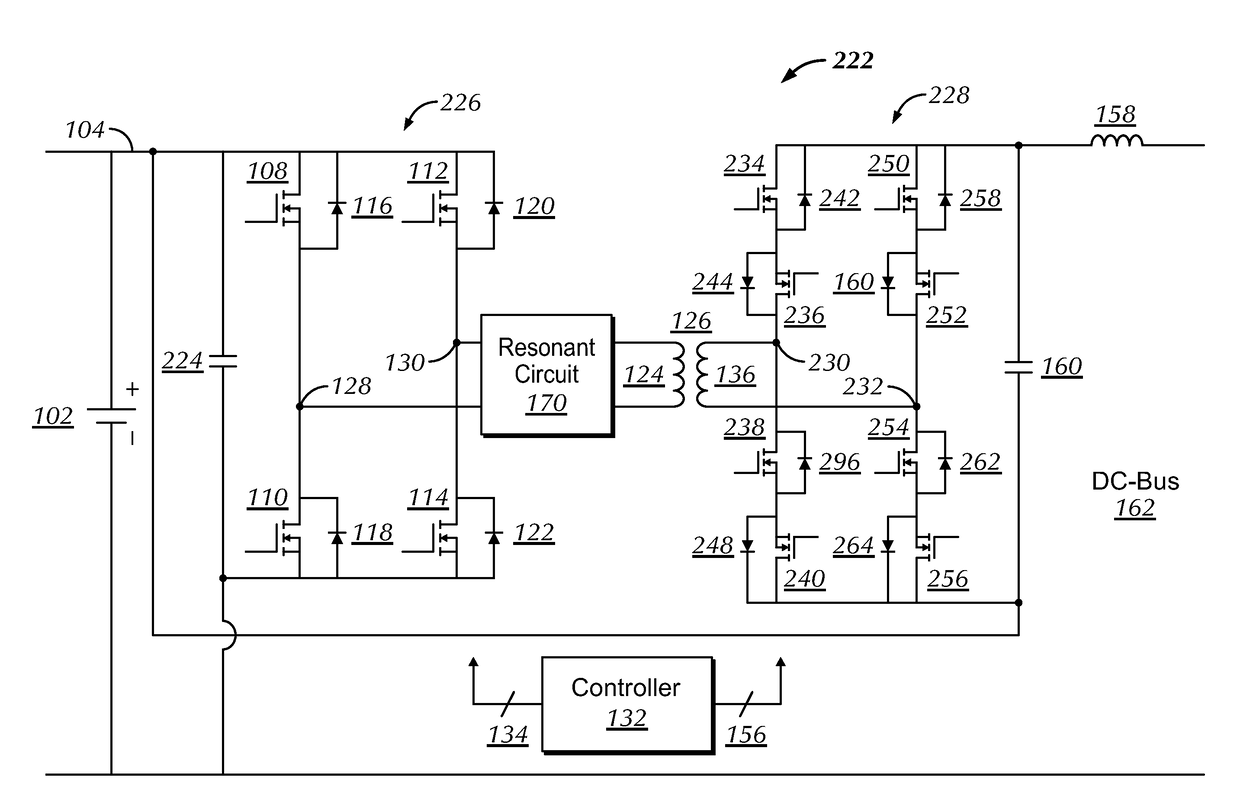
[0021]Disclosed herein is a partial power processing bi-directional, buck / boost converter topology. Bi-directional power flow allows battery charging during regenerative braking mode. The converter may be operated in either a step up (boost) or step down (buck) mode, thus allowing optimization of a DC bus voltage according to required motor speed.

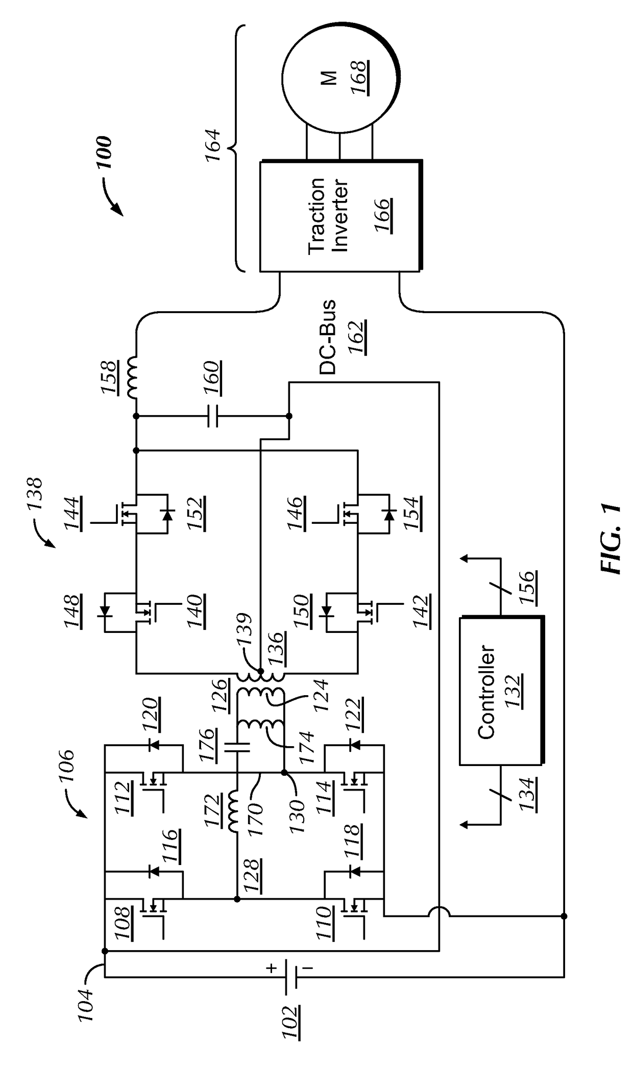
[0022]FIG. 1 illustrates a schematic diagram of a traction system 100 according to an embodiment of the present invention. The traction system 100 may be included in a vehicle such as an electric vehicle (EV), hybrid electric vehicle (HEV), or plug-in hybrid electric vehicle (PHEV). The traction system 100 may alternatively be included in a stationary electric drive system.

[0023]Traction system 100 includes an energy storage device 102. As nonlimiting examples, energy storage device 102 may be a battery, a fuel cell, or an ultracapacitor.

[0024]The energy storage device 102 is coupled via a DC link 104 to a first bridge circuit 106. The firs...


PUM


Abstract

According to some embodiments, an electronic drive circuit is disclosed. The electronic drive circuit includes an energy storage device and a first bridge circuit coupled to the energy storage device. The first bridge circuit includes at least one leg having two switches. The electronic drive circuit also includes a transformer. The transformer includes a first winding coupled to the first bridge circuit and a second winding coupled to the energy storage device through a center tap. The electronic drive circuit further includes a second bridge circuit coupled to the second winding of the transformer. The second bridge circuit includes a pair of switches operable to conduct in both directions and block voltage in both directions. The electronic drive circuit additionally includes a DC bus coupled to the second bridge circuit and a controller, which is configured to buck or boost a DC voltage from the energy storage device to supply to the DC bus as well as buck or boost a DC voltage from the DC bus to supply to the energy storage device.

Description

BACKGROUND OF THE INVENTION[0001]Embodiments of the present invention relate generally to electric drive systems, including hybrid and electric vehicles, and to stationary drives that are subject to transient or pulsed loads, and more particularly, to a bi-directional buck / boost DC-DC converter for transferring energy between an electrical storage device and a DC bus of the vehicle or drive.[0002]A hybrid electric vehicle (HEV) may combine an internal combustion engine and an electric motor powered by an energy storage device, such as a traction battery, to propel the vehicle. Typically, the electric motor of an HEV is coupled between the internal combustion engine and the transmission to take advantage of the torque increase through the transmission. Such a combination may increase overall fuel efficiency by enabling the combustion engine and the electric motor to each operate in their respective ranges of increased efficiency. Electric motors, for example, may be efficient at acce...

Claims


Application Information

Patent Timeline
IPC IPC(8): H02M3/335H02M1/08
CPCH02M1/08H02M3/33507B60L53/22H02M3/3155H02M3/3353H02M3/01H02M3/33573H02M3/33571H02M3/33561H02M3/33584H02M7/4807Y02B70/10Y02T10/70Y02T10/92Y02T10/7072Y02T90/14H02M1/0093H02M1/0058H02M7/4815Y02T10/62H02M3/335B60L7/10B60W20/14B60T2270/60B60Y2200/91B60Y2200/92H02M1/0064
Inventor ELASSER, AHMEDAGAMY, MOHAMMEDHUH, KUM KANG
Owner GENERAL ELECTRIC CO
Why Eureka
Try Eureka