Uterine Manipulator

Active Publication Date: 2017-12-14
CONMED CORP
View PDF5 Cites 6 Cited by
  • Summary
  • Abstract
  • Description
  • Claims
  • Application Information

AI Technical Summary

Benefits of technology

[0009]A particular non-limiting goal of utilization of the embodiments and implementations herein is to provide a device for manipulation of the uterus and injection of fluids or gases during laparoscopic procedures such as laparoscopic assisted vaginal hysterectomy (LAVH), total laparoscopic hysterectomy (TLH), minilap, laparoscopic tubal occlusion or diagnostic laparoscopy (and other similar procedures as should be understood by a person of ordinary skill in the art in conjunction with a review of this disclosure), and for the maintenance of a pneumoperitoneum by sealing the vagina during such procedures. In brief, the uterine manipulator device of an embodiment allows a medical practi

Problems solved by technology

For example, some or all of the discussed patents/publications/products may not be sufficiently early in time, may not reflect subjec

Method used


Image

  • Uterine Manipulator
  • Uterine Manipulator
  • Uterine Manipulator

Examples


Embodiment Construction

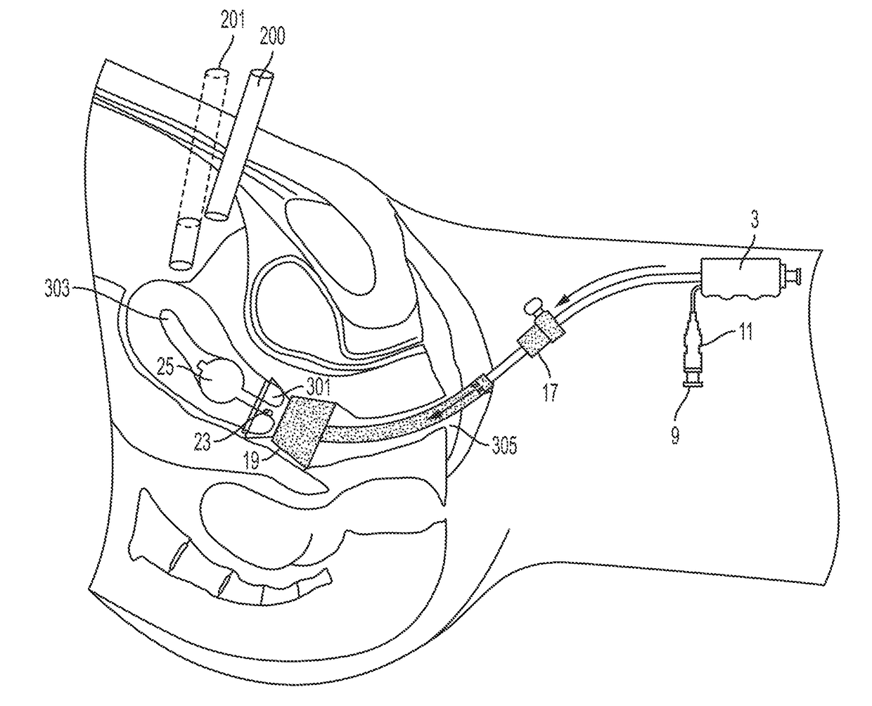
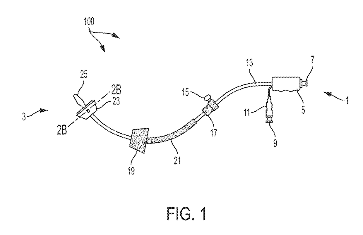
[0022]Referring to FIG. 1, in one embodiment, is a schematic representation of a uterine manipulator device 100. The uterine manipulator device 100 can include (from the distal end 1 to the proximal end 3) a handle 5, a dye injection port 7 positioned in the handle 5 (preferably through the distal end, and communicatively coupled to the intrauterine balloon 25), an inflation valve 9 (communicatively coupled to the intrauterine balloon 25), to which a syringe (e.g., 10 cc syringe, not shown) can be attached, and a pilot balloon 11 are attached to the handle 5 (preferably through the proximal end), and a cannulated manipulator tube 13. The cannulated manipulator tube 13 is curved at its proximal end and is straight at its distal end for easy introduction of the device 100, for manipulation of both retroverted and anteverted uteri, and for maintaining proper attitude of the uterus at the distal end. The cannulated manipulator tube 13 is connected to the handle 5 (preferably at the prox...


PUM


Abstract

A uterine manipulator device includes: an elongated cannulated tube comprising a proximal end and a distal end; a cervical cup having a top proximal portion of a first diameter and a base distal portion of a second smaller diameter, wherein: the base distal portion includes a hole formed therein having a perimeter including a distal end and a proximal end, and including a longitudinal axis positioned therethrough; one of the proximal end of the perimeter and the distal end of the perimeter is angled away from the longitudinal axis and the other of the proximal end of the perimeter and the distal end of the perimeter is in line with the longitudinal axis; and the elongated cannulated tube is positioned through the hole in the cervical cup.

Description

CROSS-REFERENCE TO RELATED APPLICATIONS[0001]The present application claims priority to and the benefit of U.S. Provisional Patent Application No. 62 / 347781, filed on Jun. 9, 2016, the entire contents of which are hereby incorporated by reference.FIELD OF THE INVENTION[0002]The present disclosure relates generally to devices and methods for manipulation of the uterus and cervix in surgical and diagnostic procedures.BACKGROUND[0003]Various conventional forms of uterine manipulators and vaginal cervical retractors are known. For example, U.S. Pat. No. 5,209,754 describes a vaginal cervical retractor generally consisting of a proximal (to the patient) half-length curved outer shaft (corresponding to the curve of the posterior pelvis) and a straight distal half connected to a handle, an inner cap positioned within an outer cap and a circular disc located at the proximal end of the outer tube, and an inner plastic tube positioned through the outer tube and the circular disc, inner cap an...

Claims


Application Information

Patent Timeline
IPC IPC(8): A61B17/42A61B17/00A61M5/00A61B17/02A61M25/10
CPCA61B17/4241A61B17/00234A61B2017/00557A61M25/10185A61M5/007A61B17/0218A61B17/42A61B17/3421A61M29/00
Inventor HOLBROOKS, ASHLEYFITZGERALD, RACHELLE D.YANTSIDES, CHRISTOPHERHUGHES, DAVIDWU, XIAOALI, IRTIZA
Owner CONMED CORP
Why Eureka
Try Eureka