
Flange Assembly for Heater Treaters and Other Vessels

a technology for flange assemblies and heaters, which is applied in the direction of heating types, lighting and heating apparatus, and separation processes, etc. it can solve the problems of high failure potential, high risk of failure, and the basic design of heater treater vessels that have not changed, so as to improve safety, eliminate current risks and limitations, and replace quickly and/or repair

Inactive Publication Date: 2017-12-14
GLOBAL VESSEL & TANK LLC
View PDF14 Cites 2 Cited by
  • Summary
  • Abstract
  • Description
  • Claims
  • Application Information

AI Technical Summary

Benefits of technology

The present invention provides a flange assembly that improves safety, allows for quick and efficient replacement and repair, and allows for safe operation of heater treaters and other heated separator vessels at higher MAWPs. The oval-shaped, raised face slip-on flange member has bores in spaced relationship and is mated with a raised face blind flange member. The dimensions of the two flange members are consistent, allowing them to be secured together against each other in mating face-to-face relationship. This eliminates current risks and limitations associated with conventional flange designs. The flange assembly provides greater fluid pressure sealing capacity, making it safer to operate heater treaters and other heated separator vessels at higher MAWPs.

Problems solved by technology

Nonetheless, despite such dramatic increases in size and operating parameters, the basic design of heater treaters has not changed.
Fire tube flange assemblies of conventional heater treater vessels often sustain significant damage and have high potential for failure.
As operating conditions become more extreme MAWPs increase, such flange assemblies (including, without limitation, such rubber gaskets) are frequently at risk of failing.
When said rubber gaskets degrade—particularly over time—said conventional flange assemblies can lose fluid pressure seal integrity, resulting in fluid leakage from said flange assemblies.
Such fluid leakage can negatively impact the environment surrounding a heater treater, resulting in significant remediation expense and production downtime.
Moreover, because leaking fluids can be flammable (such as oil, natural gas or other hydrocarbons) and / or toxic, such fluids can cause bodily injury or death to personnel.
Further, fire tube flange assemblies generally are not universal or interchangeable.
As a result, it is frequently difficult and / or expensive to change out fire tubes between heater treater vessels because attachment flanges often do not match from one heater treater to another.
Heater treater manufacturers generally each make their own flange pattern or design; fire tubes from one manufacturer generally cannot replace the fire tubes of another manufacturer.

Method used


Image

  • Flange Assembly for Heater Treaters and Other Vessels
  • Flange Assembly for Heater Treaters and Other Vessels
  • Flange Assembly for Heater Treaters and Other Vessels

Examples


Embodiment Construction

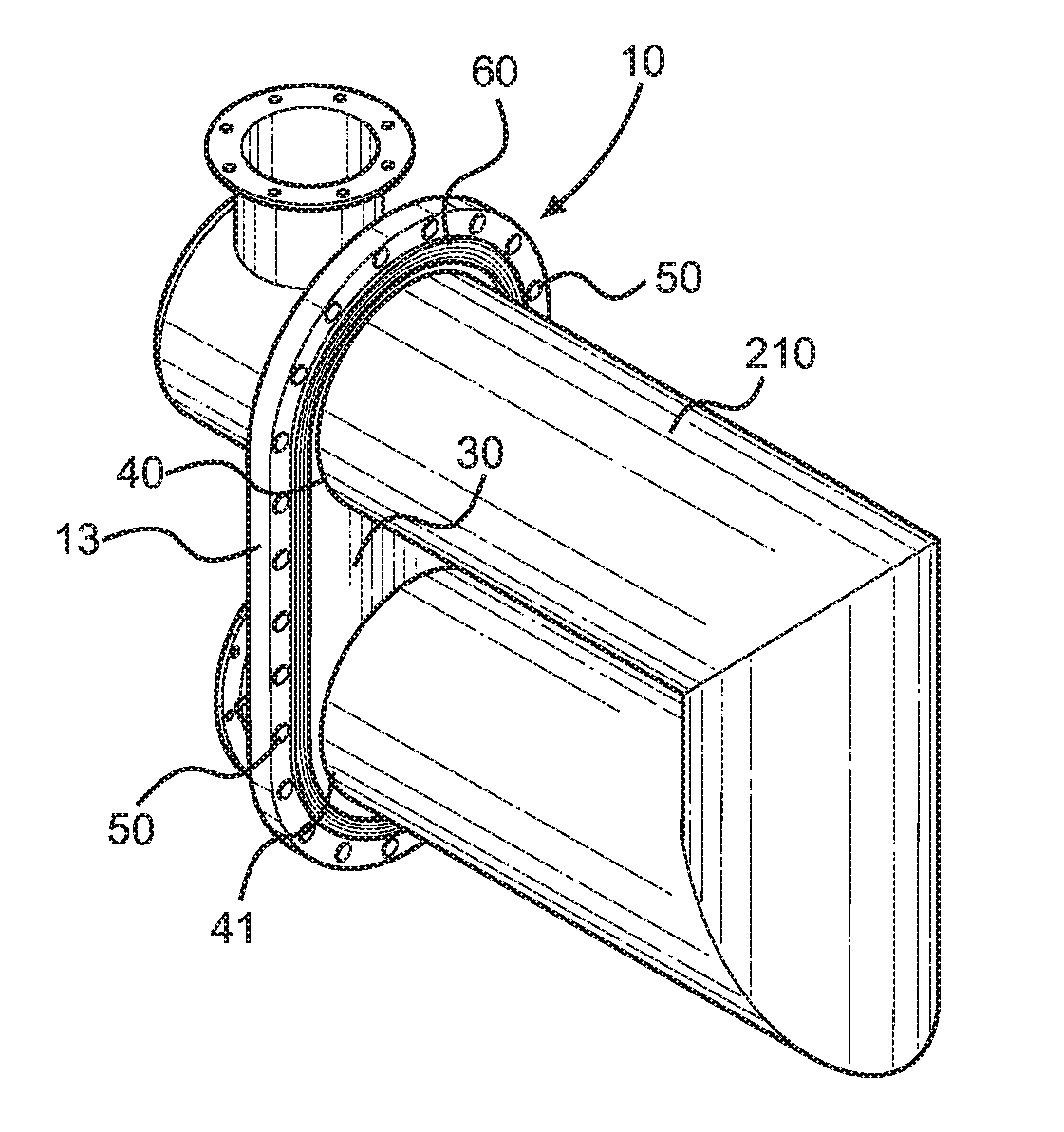
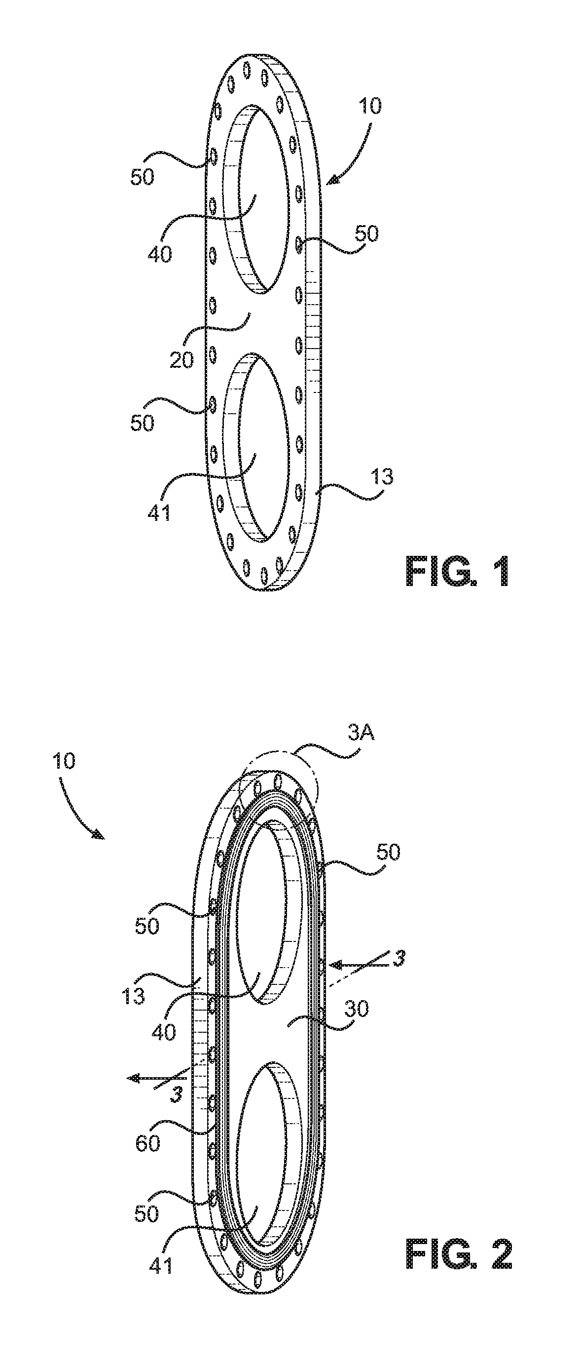
[0033]Referring to the drawings, FIG. 1 depicts a perspective view of a raised face blind flange member 10 of the present invention including, without limitation, outer surface 20 thereof. In a preferred embodiment, raised face blind flange member 10 of the present invention comprises a substantially planar member having a substantially flat outer surface 20 and oval outer shape defining circumferential edge 13.

[0034]Still referring to FIG. 1, said raised face blind flange member 10 has a plurality of holes 40 and 41 for receiving a fire tube of a conventional heater treater or other heated separator vessel, as described more fully herein. Further, a plurality of bores 50 is disposed around said oval-shaped, raised face blind flange member in spaced relationship, and provide apertures for receiving fasteners.

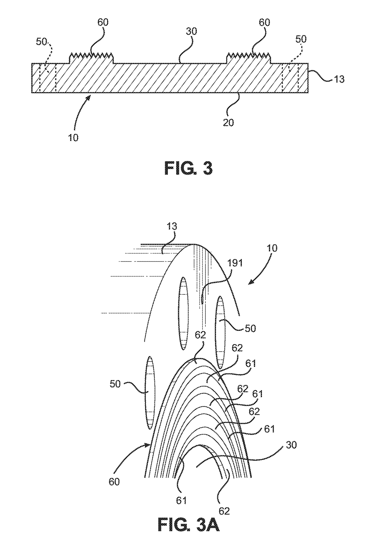
[0035]FIG. 2 depicts a side perspective view of an inner surface 30 of said raised face blind flange member 10 of the present invention (generally representing the opposite side...


PUM

PropertyMeasurementUnit
Pressureaaaaaaaaaa
diameteraaaaaaaaaa
shapeaaaaaaaaaa

Abstract

An oval-shaped flange assembly for use on heater treaters and other heated and / or pressurized separation vessels. A first substantially oval-shaped, raised face blind flange member operationally attached to a fire tube mates with an opposing oval-shaped, raised face slip-on flange member attached to a heater treater or other pressurized vessel. An alignment guide pin facilitates fast and efficient connection and disconnection of the flange members.

Description

CROSS REFERENCES TO RELATED APPLICATION[0001]Priority of U.S. Provisional Patent Application Ser. No. 62 / 349,919, filed Jun. 14, 2016, incorporated herein by reference, is hereby claimed.STATEMENTS AS TO THE RIGHTS TO THE INVENTION MADE UNDER FEDERALLY SPONSORED RESEARCH AND DEVELOPMENT[0002]NoneBACKGROUND OF THE INVENTION1. Field of the Invention[0003]The present invention pertains to a connection assembly for use in connection with vessels. More particularly, the present invention pertains to a flange assembly for use on oil and gas processing equipment. More particularly still, the present invention pertains to a flange assembly for use with fire tubes of heat-treating separator vessels.2. Brief Description of the Prior Art[0004]Generally, processing equipment in the oil and gas industry has remained substantially unchanged for many years with very little variation in design or innovation. One such piece of equipment that has remained essentially unchanged over time is the emulsi...

Claims


Application Information

Patent Timeline
Patent Type & Authority Applications(United States)
IPC IPC(8): B21D19/04B01D21/34F24F13/02B01D21/00
CPCB21D19/046B01D21/34B01D21/0003B01D2221/04F24F13/0209B01D21/009
Inventor ALLEN, KRIEG M.
Owner GLOBAL VESSEL & TANK LLC
Learn More