Sealing member and sealing structure

a sealing member and sealing technology, applied in the direction of engine seals, mechanical devices, engine components, etc., can solve the problems of low sealing durability, easy abrasion of the o-ring, increased rotational resistance of the rotary shaft, etc., to achieve excellent abrasion suppression on the sealing surface, easy to handle, and excellent sealing structure

Active Publication Date: 2017-12-14
SOMAR CORP
View PDF5 Cites 3 Cited by
  • Summary
  • Abstract
  • Description
  • Claims
  • Application Information

AI Technical Summary

Benefits of technology

[0020]According to the present disclosure, a sealing member which is easy to handle, is suitable for sealing between various members, and is excellent in suppressing abrasion on the seal surface, and a sealing structure may be provided.

Problems solved by technology

However, in a case in which sealing between members is carried out using an O-ring and one of the members is a rotary shaft, the rotational resistance of the rotary shaft is increased and moreover, abrasion of the O-ring occurs easily.
Therefore, there is a problem in that the sealing durability is low.
Since grease or the like is loaded in the oil seal, there is concern that the oil component may leak out to pollute the surroundings.
Further, since sealing is carried out by utilizing the contact pressure between the lip portion made of rubber and the rotary shaft, dust is generated due to abrasion and there is a problem in that the sealing durability is low.

Method used

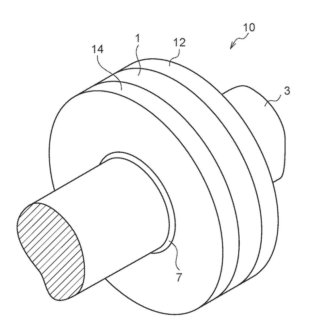
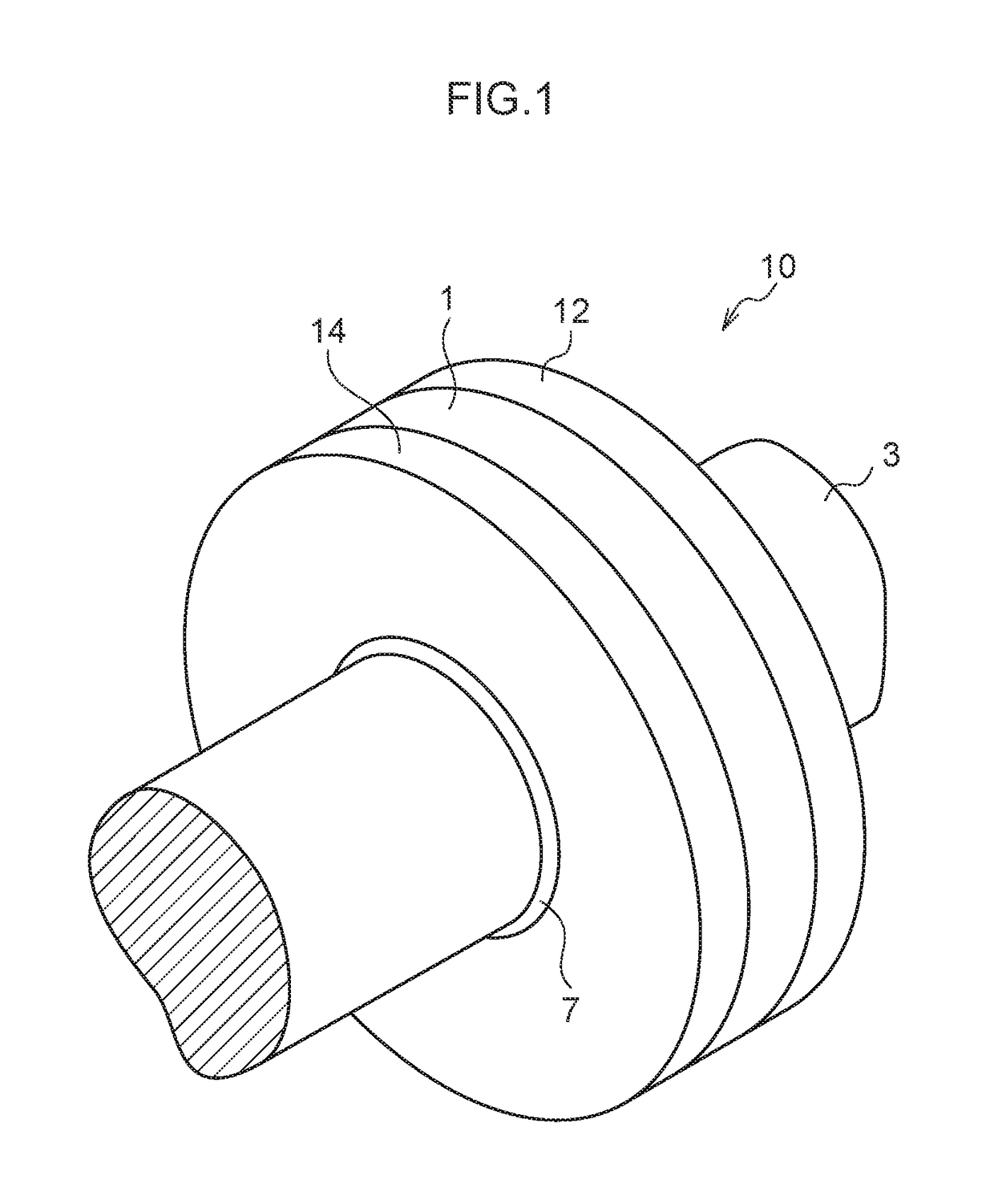
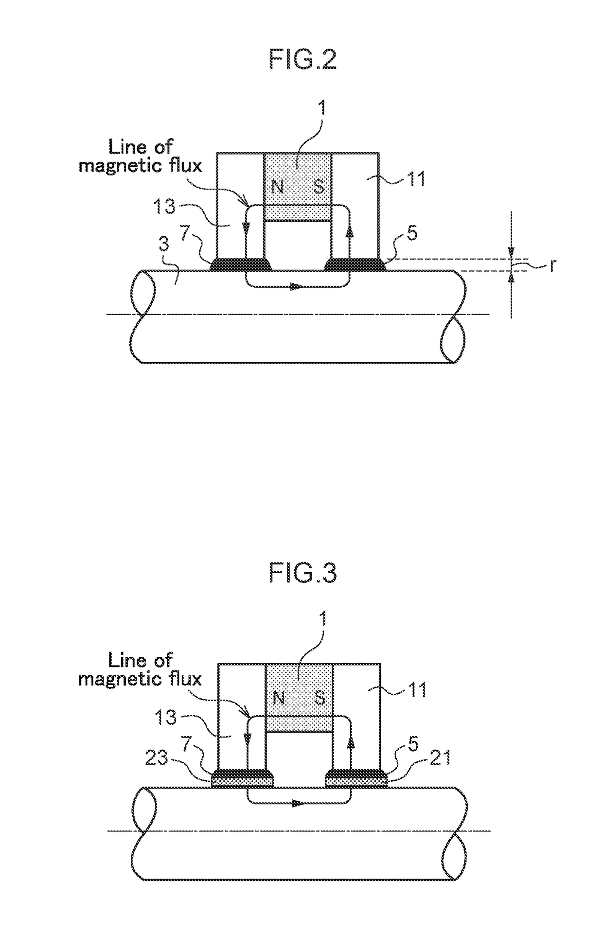

Image

  • Sealing member and sealing structure
  • Sealing member and sealing structure
  • Sealing member and sealing structure

Examples


example 1

[0146]1. Removal of Dispersion Medium from Magnetic Fluid

[0147]50 mL of a magnetic fluid (trade name: EXP.12038, manufactured by Ferrotec Corporation; magnetic particles covered with a dispersant (magnetic particles: magnetite, average primary particle diameter: 15 nm, dispersant: sodium oleate), dispersion medium: isoparaffin) were prepared, and 50 mL of ethanol (85% aqueous solution) were added thereto. The resulting mixture was stirred thoroughly, thereby aggregation-precipitating magnetic particles. The precipitation time was set to 24 hours. Thereafter, ethanol was removed by filtration, to obtain an aggregated precipitate of magnetic particles.

[0148]2. Production of Magnetic Powder

[0149]The aggregated precipitate thus obtained was flattened, and placed in a convection oven having a temperature elevated to 115° C. The aggregated precipitate was dried by heating in the convection oven for 8 hours, and then left to stand to cool for 2 hours. The magnetic particles after drying we...

example 2

[0191]1. Production of Magnetic Powder

[0192]From a magnetic fluid (trade name: EXP.12038, manufactured by Ferrotec Corporation; magnetic particles covered with a dispersant (magnetic particles: magnetite, average primary particle diameter: 15 nm, dispersant: sodium oleate), dispersion medium: isoparaffin), the dispersion medium was removed according to the same method as in Example 1, to obtain an aggregated precipitate of magnetic particles. Then, using the aggregated precipitate thus obtained, a magnetic powder was prepared. The average primary particle diameter of the magnetic powder obtained by pulverization was 26 nm.

[0193]2. Production of Magnetic Powder Composition

[0194]An acrylonitrile-butadiene rubber (NBR; trade name: N230SV, manufactured by JSR Corporation) as a main agent, a vulcanizing agent (powdery sulfur), N-(tert-butyl)-2-benzothiazolesulfenamide (TBBS; vulcanization accelerator), zinc oxide (vulcanization accelerating aid), stearic acid (processing aid), and magnet...


PUM

PropertyMeasurementUnit
average primary particle diameteraaaaaaaaaa
thicknessaaaaaaaaaa
particle sizeaaaaaaaaaa

Abstract

An embodiment of the present invention provides a sealing member including a magnetic powder and at least one selected from the group consisting of a rubber material and a resin material, the magnetic powder being obtained by removing a dispersion medium from a magnetic fluid including magnetic particles, a dispersant and dispersion medium.

Description

CROSS-REFERENCE TO RELATED APPLICATIONS[0001]This application is the National Stage of International Application No. PCT / JP2015 / 085883, filed 22 Dec. 2015, having the title “SEALING MEMBER AND SEALING STRUCTURE”, which claims the benefit of and priority to Japanese Application No. 2014-265460, filed on 26 Dec. 2014, the contents of all of which are incorporated by reference as if fully set forth herein.TECHNICAL FIELD[0002]The present disclosure relates to a sealing member and a sealing structure.BACKGROUND ART[0003]Conventionally, research has been widely conducted related to techniques for sealing between members to prevent, for example, oil leakage. For example, a method of sealing using an O-ring made of rubber as shown in FIG. 7 is widely known from the viewpoints of simplicity of the structure and the like. In this method, sealing is achieved by utilizing a repelling force (contact pressure) of the O-ring, the repelling force being generated by applying pressure as appropriate...

Claims


Application Information

Patent Timeline
Patent Type & Authority Applications(United States)
IPC IPC(8): F16J15/43F16J15/14
CPCF16J15/14F16J15/43
Inventor ISHIZAKI, HIROHISAOCHIAI, AKIRA
Owner SOMAR CORP
Why Eureka
Try Eureka