Optical device, display unit, and electronic apparatus
- Summary
- Abstract
- Description
- Claims
- Application Information
AI Technical Summary
Benefits of technology
Problems solved by technology
Method used
Image

Examples
first embodiment
1. FIRST EMBODIMENT
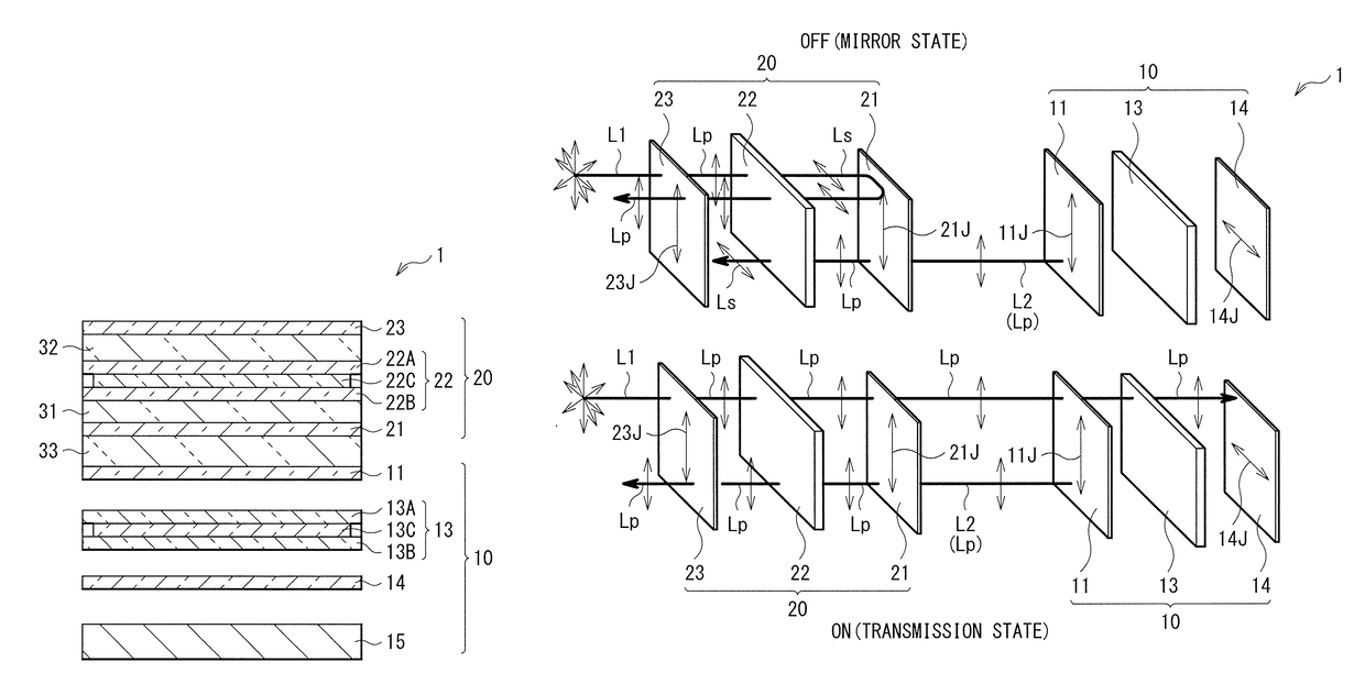
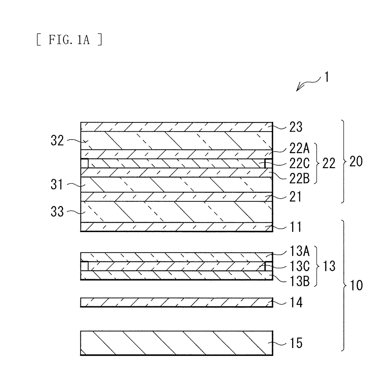
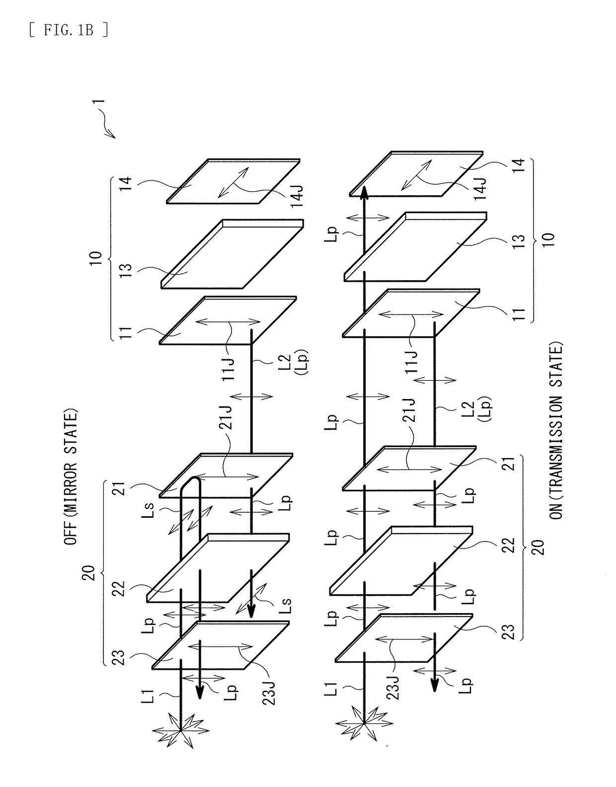
[0069]FIG. 1 illustrates a cross-sectional configuration of a display unit 1 as one embodiment of the present disclosure. This display unit 1 includes two liquid crystal panels that are overlapping each other, and is thereby configured to be able to perform switching between a screen state and a mirror surface state. In such a display unit, light that has passed through the liquid crystal panel provided in a display switching section and an absorption-type polarization plate disposed on the viewer side is to be visually recognized in both the screen state and the mirror surface state. Therefore, a visually-recognized state is determined on the basis of transmission characteristics of the absorption-type polarization plate disposed on the viewer side and the liquid crystal panel in the display switching section. Accordingly, in the existing display unit described above, coloring may occur in some cases due to the wavelength dispersion of the absorption-type polariz...
second embodiment
2. SECOND EMBODIMENT
[Configuration of Display Unit 2]
[0119]FIG. 2 illustrates a schematic configuration of a display unit 2 according to a second embodiment of the present disclosure. The display unit 2 has a configuration similar to the configuration of the display unit 1 according to the foregoing first embodiment except that the transmission polarization axis 21J of the reflection-type polarization plate 21 and the transmission polarization axis 23J of the absorption-type polarization plate 23 are orthogonal to each other in the display switching section 20.
[Operation of Display Unit 2]
[0120]Also in this display unit 2, for example, by controlling intensity of an electric field to be applied to the liquid crystal layer 22C of the liquid crystal panel 22 in the display switching section 20 or by performing switching between presence and absence of the application of the electric field, it is possible to cause the display switching section 20 to be in a transmission state (the scre...
third embodiment
3. THIRD EMBODIMENT
[Configuration of Display Unit 3]
[0129]FIG. 3 illustrates a cross-sectional configuration of a display unit 3 according to a third embodiment of the present disclosure. The display unit 3 has a configuration similar to the configuration of the display unit 1 according to the foregoing first embodiment except that a position at which the absorption-type polarization plate 11 is disposed is changed in the display section 10.
[0130]Specifically, in the display unit 3, the absorption-type polarization plate 11 is disposed between the substrate 13A and the liquid crystal layer 13C instead of being disposed between the reflection-type polarization plate 21 and the substrate 13A.
[Workings and Effects of Display Unit 3]
[0131]Also in the display unit 3, it is possible to perform the switching between the screen state (the image display mode) and the mirror surface state (the external light reflection mode) by the display switching section 20 as in the foregoing first embodi...
PUM
 Abstract
Description
Claims
Application Information