Control device for vehicle heater

Active Publication Date: 2017-12-21
TOYOTA JIDOSHA KK
View PDF0 Cites 2 Cited by
  • Summary
  • Abstract
  • Description
  • Claims
  • Application Information

AI Technical Summary

Benefits of technology

[0011]According to the above aspect, a hysteresis is provided between prohibition of execution of the heater energization control and permission of execution of the heater energization control. Therefore, it becomes possible to prevent the heater energization control from bein

Problems solved by technology

However, when heat noises are generated in the camera image taken in the nighttime as described before, it is difficult for the driving assist system to distinguish the heat noises from the red points indicative of the tail lamps of the leading

Method used


Image

  • Control device for vehicle heater
  • Control device for vehicle heater
  • Control device for vehicle heater

Examples


Example

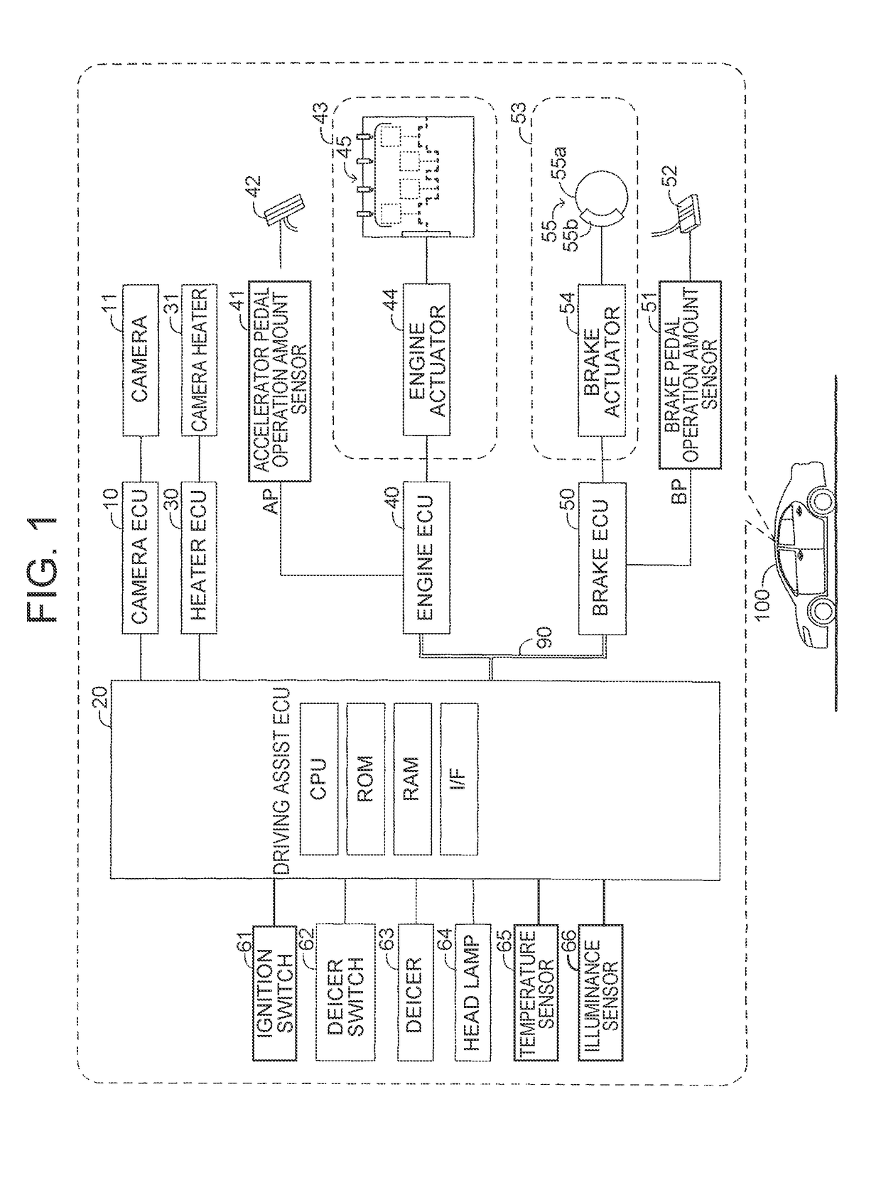
[0026]Hereinafter, a window glass heating device according to an embodiment of the present disclosure (which is referred to as “the device of the embodiment”) will be described. The device of the embodiment is applied to a vehicle 100 illustrated in FIG. 1. The device of the embodiment includes a camera ECU 10, a driving assist ECU 20, a heater ECU 30, an engine ECU 40, and a brake ECU 50.

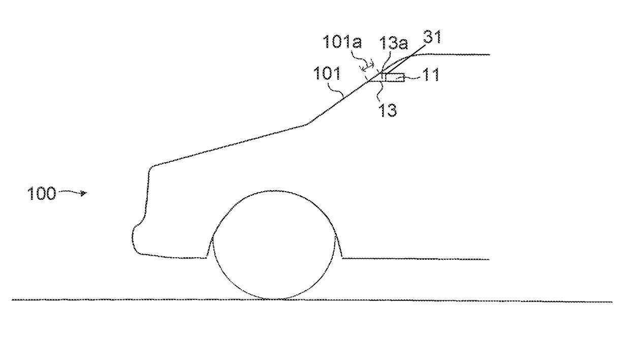
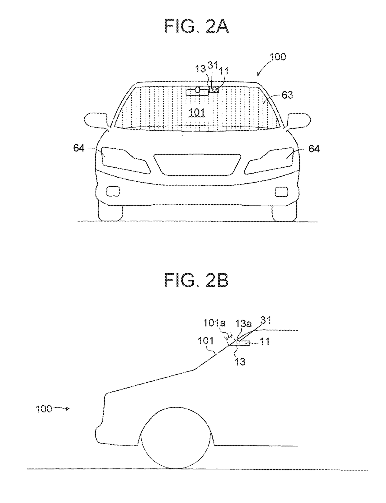
[0027]The vehicle 100 includes a camera 11. The camera 11 is a well-known charge-coupled device (CCD) camera or complementary Metal Oxide Semiconductor (CMOS) camera. The camera 11 is disposed inside the vehicle 100, i.e., inside a windshield glass 101 that is one of the front window glasses of the vehicle 100 as illustrated in FIG. 2B. The camera 11 is supported to the vehicle 100 with a bracket (supporting member) 13. The bracket 13 is made of a resin material.

[0028]The camera 11 photographs the outside of the vehicle 100 from the inside of the vehicle 100 through the windshield glass 101. As ill...


PUM


Abstract

A control device for a vehicle heater includes: a camera; a heater configured to heat a portion of the window glass located in front of the camera; a temperature sensor configured to acquire a camera temperature; an illuminance acquisition unit configured to acquire an illuminance outside the vehicle; and a control unit configured to determine that a control prohibition condition to prohibit execution of the heater energization control is satisfied when the camera temperature is equal to or larger than a prohibition threshold temperature, execute the heater energization control when execution of the heater energization control is requested, prevent execution of the heater energization control when the control prohibition condition is satisfied, and when the illuminance is lower than a threshold illuminance, set the prohibition threshold temperature to be lower than when the illuminance is equal to or larger than the threshold illuminance.

Description

CROSS-REFERENCE TO RELATED APPLICATIONS[0001]This application claims priority to Japanese Patent Application No. 2016-120361 filed on Jun. 17, 2016 which is incorporated herein by reference in its entirety including the specification, drawings and abstract.BACKGROUND1. Technical Field[0002]The present disclosure relates to a control device for a vehicle heater.2. Description of Related Art[0003]There is known a system for performing driving assist control (which is referred to as “a driving assist system” below) that assists a driver driving a vehicle. The driving assist system includes a camera photographing a forward view of the vehicle through a window glass (for example, a windshield glass or a rear glass). The driving assist system performs driving assist control using an image (which is referred to as “a camera image” below) photographed with the camera. The conventional assist system further includes a heater device to prevent or remove fogging on a portion of the window glas...

Claims


Application Information

Patent Timeline
IPC IPC(8): B60S1/02H04N7/18H05B1/02B60J1/00H05B3/84
CPCB60S1/026B60J1/002H05B3/84H04N7/183H05B1/0236B60S1/56H05B2203/008
Inventor NAGAE, HAJIME
Owner TOYOTA JIDOSHA KK
Why Eureka
Try Eureka