Modular packaging system for a lubricant condition monitor

a condition monitor and module technology, applied in the field of fluid analysis, can solve the problems of lubricating fluid degradation or contamination by internal or external sources, accumulation of component wear debris, affecting the lifetime and maintenance requirements of oil-wetted components,

Active Publication Date: 2017-12-21
SIKORSKY AIRCRAFT CORP
View PDF3 Cites 11 Cited by
  • Summary
  • Abstract
  • Description
  • Claims
  • Application Information

AI Technical Summary

Benefits of technology

[0019]Technical function that is achieved by the combination of features described above includes a modular packaging system with selectively removable / replaceable sensor module assemblies. Individual module assemblies can be adjusted, repaired, or upgraded independently, as needed and prevents a single failed module assembly in a lubricant condition monitor from rendering the monitor non-functional.

Problems solved by technology

Lubricating fluids can become degraded or contaminated by internal or external sources or accumulate component wear debris due to pitting, spalling, corrosion-induced fatigue, or other mechanisms.
Further, water infiltration or chemical changes can degrade the lubricant and can affect oil-wetted component lifetimes and maintenance requirements.
The off-line lubricant analysis can be slow, labor intensive, expensive and error prone.
However, this metallic debris monitoring is not sensitive to detecting non-ferrous debris such as magnesium alloy or aluminum alloy.
As a result, there exists a significant risk for failure of a single electrical component in a sensor assembly that can render the entire package assembly non-functional.
Furthermore, the mechanical packaging needed to interface with these aircraft systems often requires the precision manufacture of exotic materials, substantially inflating the cost and lead time associated with upgrading core sensing capability.

Method used


Image

  • Modular packaging system for a lubricant condition monitor
  • Modular packaging system for a lubricant condition monitor
  • Modular packaging system for a lubricant condition monitor

Examples


Embodiment Construction

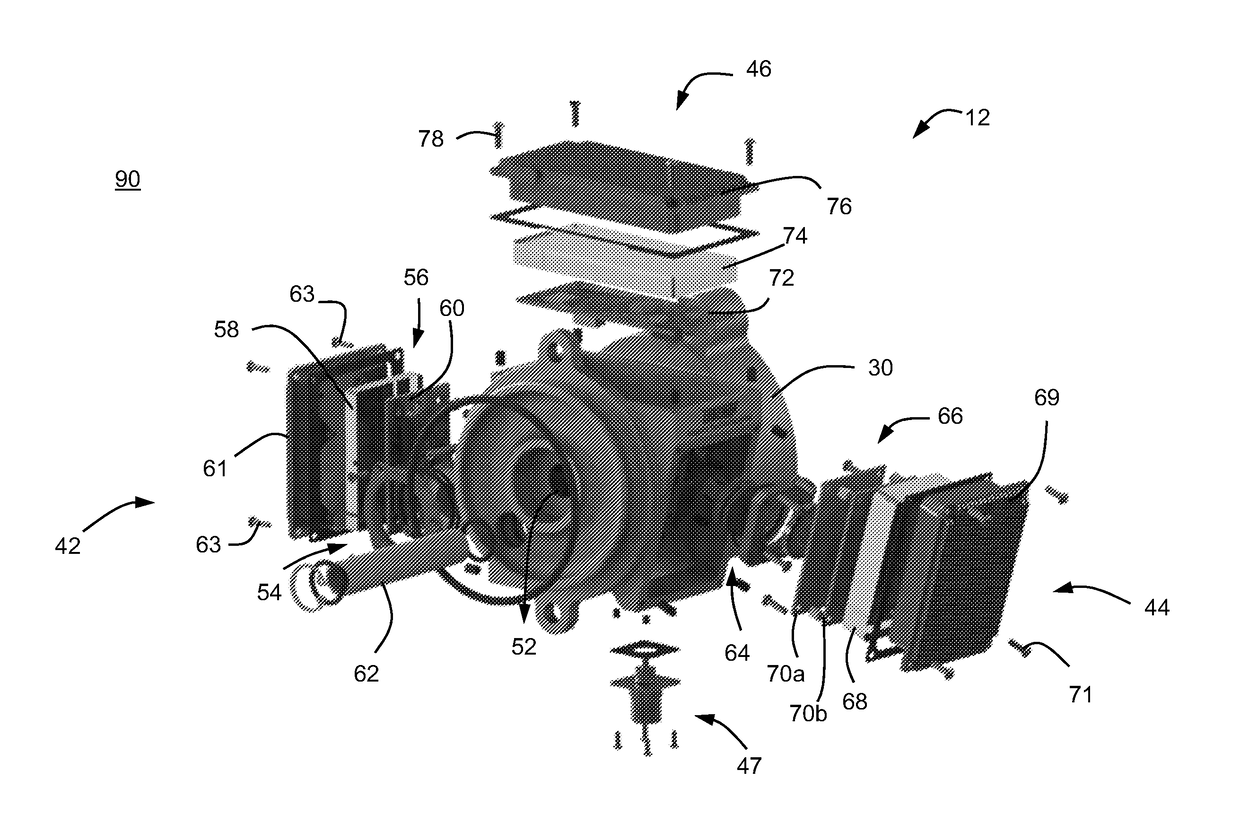
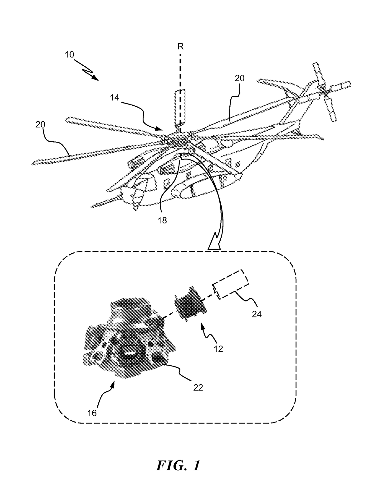
[0029]Referring to the drawings, FIG. 1 illustrates an exemplary vehicle with a gearbox, e.g., a helicopter or aircraft 10 having gearbox 16 with a modular lubricant condition assessment monitor 12 (hereinafter “monitor 12”) in accordance with an embodiment of the invention. Monitor 12 is a modular packaging assembly that integrates a plurality of self-contained sensor module assemblies for providing lubrication condition assessment and wear debris detection of a lubricant in gearbox 16. For clarity, lubricant can include oil, or other lubricating fluids. As shown, exemplary aircraft 10 includes main rotor assembly 14 that is driven about an axis of rotation R by one or more engines 18. Main rotor assembly 14 includes a multiple of rotor blades 20 mounted to rotor assembly 14 and are driven for rotation about axis R through a main gearbox 16. Monitor 12 can be embedded as an in-line, on-line or off-line sensor that integrates both lubricant condition monitoring and wear debris detec...


PUM

PropertyMeasurementUnit
optical inspectionaaaaaaaaaa
axis of rotationaaaaaaaaaa
thermally conductiveaaaaaaaaaa

Abstract

An apparatus for assessment of a fluid system includes a scaffold housing with a plurality of internal cavities; a debris monitor module assembly to be selectively inserted into a first cavity of the plurality of internal cavities, the debris monitor module assembly to determine wear debris information in a lubricant; a lubricant condition monitor module assembly to be selectively inserted into a second cavity of the plurality of internal cavities, the lubricant condition monitor module assembly to determine lubricant condition information in the lubricant; and a processing module assembly that is configured to be selectively inserted into a third cavity of the plurality of internal cavities, the processing module assembly to provide communication to an external interface of at least one of the wear debris information and the lubricant condition information.

Description

STATEMENT REGARDING FEDERALLY SPONSORED RESEARCH OR DEVELOPMENT[0001]This invention was made with Government support with the United States Army under Contract No. W911W6-10-2-0007. The Government therefore has certain rights in this invention.BACKGROUND[0002]The subject matter disclosed herein relates generally to the field of fluid analysis and, more particularly, to a modular packaging system for mounting sensor modules within an integrated lubricant quality assessment and debris monitoring device.DESCRIPTION OF RELATED ART[0003]Aircraft mechanical components require wear protection fluids, for example, fluids such as drive train lubricants and engine oils to keep the aircraft's components operating in an efficient and safe manner. Lubricating fluids can become degraded or contaminated by internal or external sources or accumulate component wear debris due to pitting, spalling, corrosion-induced fatigue, or other mechanisms. Further, water infiltration or chemical changes can deg...

Claims


Application Information

Patent Timeline
Patent Type & Authority Applications(United States)
IPC IPC(8): G01N15/06G01N33/28G01N15/10
CPCG01N15/0656G01N2015/1062G01N33/2888G01N33/2858G01N2015/1486
Inventor TURE, CODY MICHAELMINNELLA, CHRISTOPHER M.
Owner SIKORSKY AIRCRAFT CORP
Why Eureka
Try Eureka