Bio-energy power system

Active Publication Date: 2017-12-21
KOHANE TECH
View PDF0 Cites 3 Cited by
  • Summary
  • Abstract
  • Description
  • Claims
  • Application Information

AI Technical Summary

Benefits of technology

The patent describes a system that can increase the amount of bio-energy available for human use. This is done by using a renewable process involving breeding fruit fly strains that store high levels of energy. This energy can be made available for human use in an efficient way, similar to fossil fuels and independent of environmental conditions. By placing selection pressures on the fruit flies, the system can increase the availability of bio-energy and enhance the survival of future generations. The method involves culturing the flies in a vac system and making select crosses between different strains. This process can be monitored over time to select strains with enhanced energy availability.

Problems solved by technology

However, these energy sources come with significant environmental and economic risks.
However, these forms of energy also have major drawbacks.
For example, wind turbines can collect renewable energy, but birds and bats are known to collide with the turbines.
While this is a renewable energy source, much of the plant is wasted in the process, and thousands of acres of fertile farmland are dedicated to growth of corn for fuel instead of food.
Additionally, the energy harvested from renewable sources often cannot be stored; it must immediately be transferred to the grid.
And while current scientific advancements, such as storage of solar energy in flow batteries, hydrogen, or molten salt, are making it more likely that renewable sources may be storable, these advances are slow and will not be viable commercial options for years to come.
Another problem associated with many types of renewable energy is access to the power grid.
Dispersed energy production, such as with fuel cell, solar, and wind technologies, has limitations with respect to the grid because the energy produced is not maximized at one site or locality and is thus not immediately available to the grid.
However, one major drawback is that these energy sources may not be renewable and pose great environmental challenges.

Method used


Image

  • Bio-energy power system
  • Bio-energy power system
  • Bio-energy power system

Examples


Embodiment Construction

[0048]Various embodiments will be described in detail with reference to the drawings, wherein like reference numerals represent like parts and assemblies throughout the several views. Reference to various embodiments does not limit the scope of the claims attached hereto. Additionally, any examples set forth in this specification are not intended to be limiting and merely set forth some of the many possible embodiments for the appended claims. It is understood that various omissions and substitutions of equivalents are contemplated as circumstances may suggest or render expedient, but these are intended to cover applications or embodiments without departing from the spirit or scope of the claims attached hereto. Also, it is to be understood that the phraseology and terminology used herein are for the purpose of description and should not be regarded as limiting.

[0049]Overview

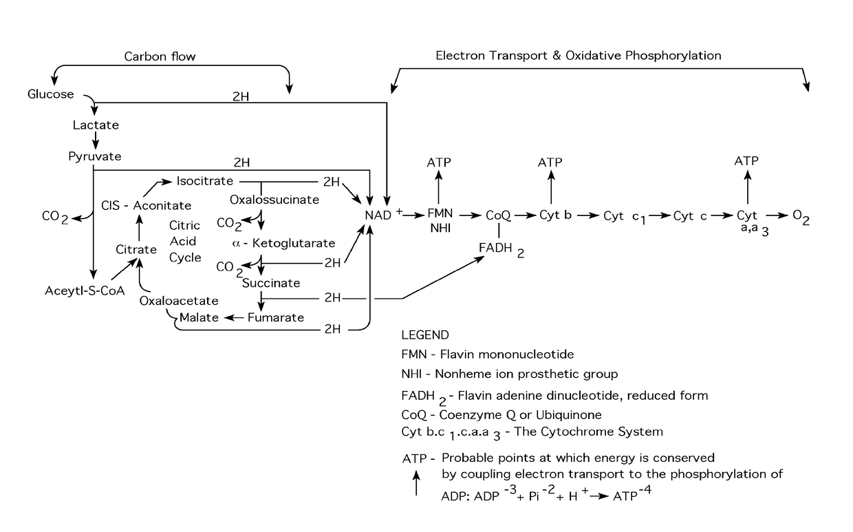
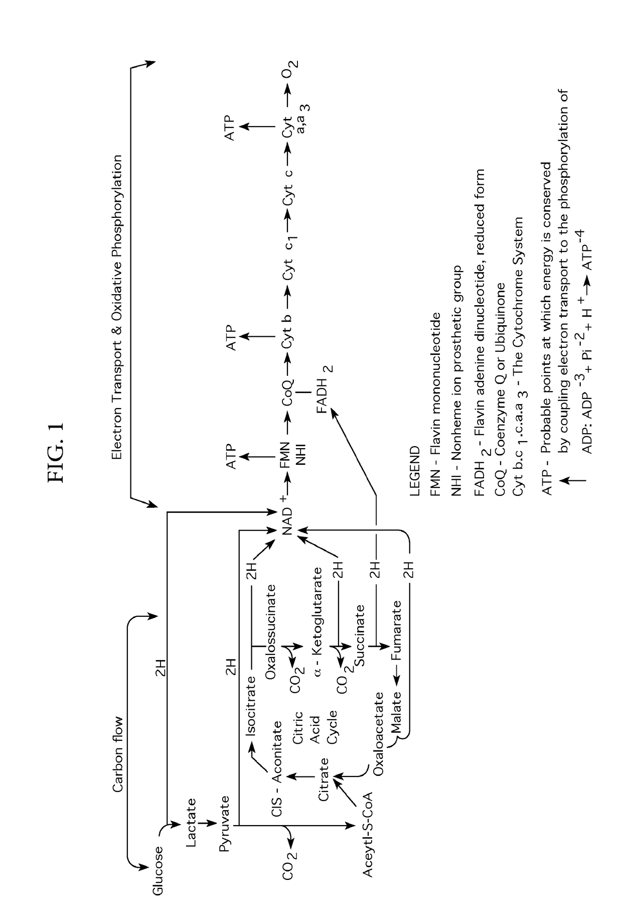
[0050]At the most basic level, humans require moving electrons and, possibly, moving protons as their primary...


PUM


Abstract

A bio-energy power system comprising a selection process, an extraction process, and a transfer process. More specifically, a bio-energy power system that uses a selection process to create an energy enhanced organism. In some embodiments, the energy is extracted and consumed using an extraction process to create an energy rich homogenate from the energy enhanced organism and a transfer process to transfer the energy from the energy rich homogenate to the grid or to an energy storage device. In other embodiments, the energy enhanced organism is kept alive and the energy is extracted and consumed using a pure quartz water system for extraction and a transfer process to transfer the energy from the pure quartz water system to the grid or to an energy storage device.

Description

CROSS-REFERENCE TO RELATED APPLICATION[0001]This application claims the benefit of U.S. Provisional Patent Application No. 62 / 088,349, filed on Dec. 5, 2014, titled BIO-ENERGY POWER SYSTEM.FIELD OF THE DISCLOSURE[0002]The disclosed invention generally relates to bio-energetics. More specifically, the disclosed process and method involves enhancing primary bio-energy systems, such as fruit fly colonies, and harvesting a high yield of electrons, protons, and ATP from the enhanced bio-energy system. The harvested energy can then immediately be made available or it can be stored for future human use.BACKGROUND OF THE INVENTION[0003]At this time, the best sources of energy and stored energy are fossil fuels, coal, gas, oil and nuclear. These contain high levels of energy that can be released for human use. However, these energy sources come with significant environmental and economic risks. Therefore, alternative energy is an important field of work, and many forms of alternative energy ...

Claims


Application Information

Patent Timeline
IPC IPC(8): H01M8/16H01M8/20H02N11/00H02N99/00
CPCH01M8/16H02N99/00H02N11/002H01M8/20Y02E60/50
Inventor KOHANE, MICHAEL
Owner KOHANE TECH
Why Eureka
Try Eureka