Apparatus for mm-wave radiation generation utilizing whispering gallery mode resonators

a technology of mm-wave radiation and whispering gallery mode, which is applied in the direction of electrical apparatus, accelerators, tubes with resonator modulated electron streams, etc., can solve the problems of limiting the output power to the level already achieved with traditional devices, requiring relativistic electron beams, and complicated magnetic field profiles. achieve the effect of reducing current, limiting output power, and high power operation

Inactive Publication Date: 2017-12-21
THE BOARD OF TRUSTEES OF THE LELAND STANFORD JUNIOR UNIV
View PDF0 Cites 4 Cited by
  • Summary
  • Abstract
  • Description
  • Claims
  • Application Information

AI Technical Summary

Benefits of technology

[0003]The present invention provides a vacuum tube technology, where the device size is inherently bigger than the wavelength it is operating on. It provides an improvement upon the output circuit of Gyrocons (U.S. Pat. No. 3,885,193 and U.S. Pat. No. 4,019,088) and Trirotrons (U.S. Pat. No. 4,210,845 and U.S. Pat. No. 4,520,293) to make them suitable for high power operation with low beam voltage in the mm-wave and THz part of the electromagnetic spectrum. In Gyrocons, an axial DC electron beam, originating from a pierce gun, is helically deflected, by exciting two orthogonal polarizations in a TM11 deflecting resonator with a 90° phase difference. The beam arrives at the output resonator as a current wave rotating around the axis of symmetry, and excites a traveling electromagnetic wave. The synchronism condition is given by ωRF=nωLO, where ωLO is the angular frequency of the deflecting resonator, ωRF is angular frequency of the generated signal in the output resonator, and n is the number of azimuthal variations of the target eigenmode in the output resonator. However, the type of output cavities traditional Gyrocons used employed beam pipes shielded with aluminum foils to contain the fields, thus requiring relativistic electron beams. Additionally, a complicated magnetic field profile was necessary to get the beam through those beam pipes. Scaling those designs to higher frequencies requires reducing the current dramatically, and therefore limiting the output power to levels already achieved with traditional devices. In Trirotrons, an annular radially expanding DC electron beam is radially velocity modulated using a ring resonator operating at ωLO and is intercepted at an output resonator operating at ωRF=nωLO, and having n times the number of azimuthal variation as the modulating resonator. Similarly to Gyrocons, scaling the output resonator of a Trirotron into the mm-wave and THz part of the electromagnetic spectrum requires a very narrow beam pipe and therefore limited current.
[0004]In a whispering gallery mode resonator, the electromagnetic waves bounce around a central axis, supported by the guiding surface of the resonator. Because of such a field configuration, the inner part of the resonator can be completely open without the fields leaking, as in a ring resonator. Unlike Gyrocons and Trirotrons, the whispering gallery mode resonator also acts as the collector. When the device is configured for frequency multiplication from X-band (8-12 GHz) to V-band (50-75 GHz) or W-Band (75 GHz-110 GHz), the dimensions of the output resonator allow for a device that is small enough that beam expansion is minimal, even without any focusing magnetic field, but big enough to allow for significant current to go through. There is therefore no need for a narrow beam pipe, or any sort of magnetic focusing or beam guidance compared to existing Gyrocons and Trirotrons.

Problems solved by technology

However, the type of output cavities traditional Gyrocons used employed beam pipes shielded with aluminum foils to contain the fields, thus requiring relativistic electron beams.
Additionally, a complicated magnetic field profile was necessary to get the beam through those beam pipes.
Scaling those designs to higher frequencies requires reducing the current dramatically, and therefore limiting the output power to levels already achieved with traditional devices.

Method used


Image

  • Apparatus for mm-wave radiation generation utilizing whispering gallery mode resonators
  • Apparatus for mm-wave radiation generation utilizing whispering gallery mode resonators
  • Apparatus for mm-wave radiation generation utilizing whispering gallery mode resonators

Examples


Embodiment Construction

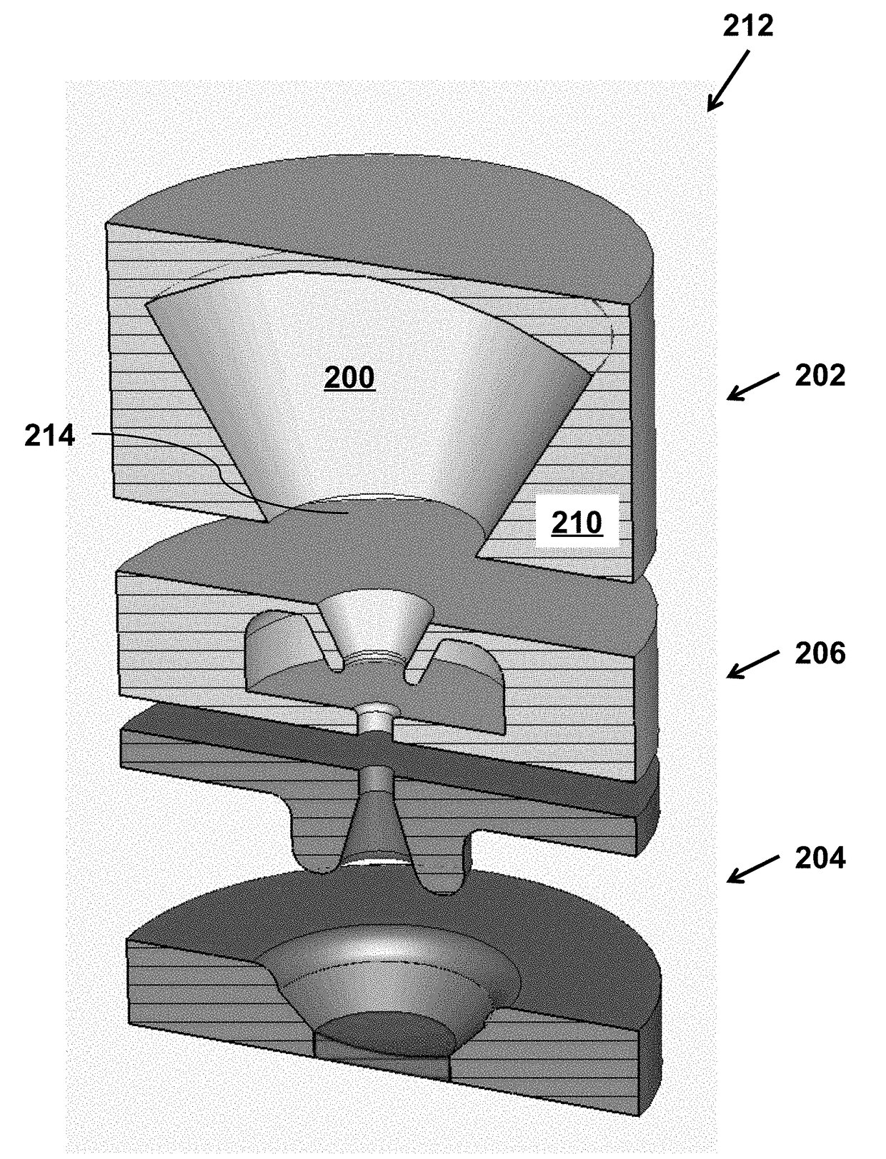
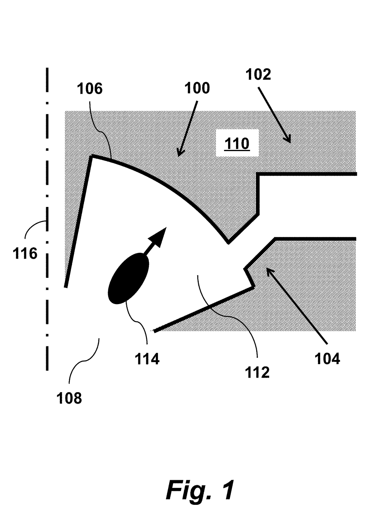
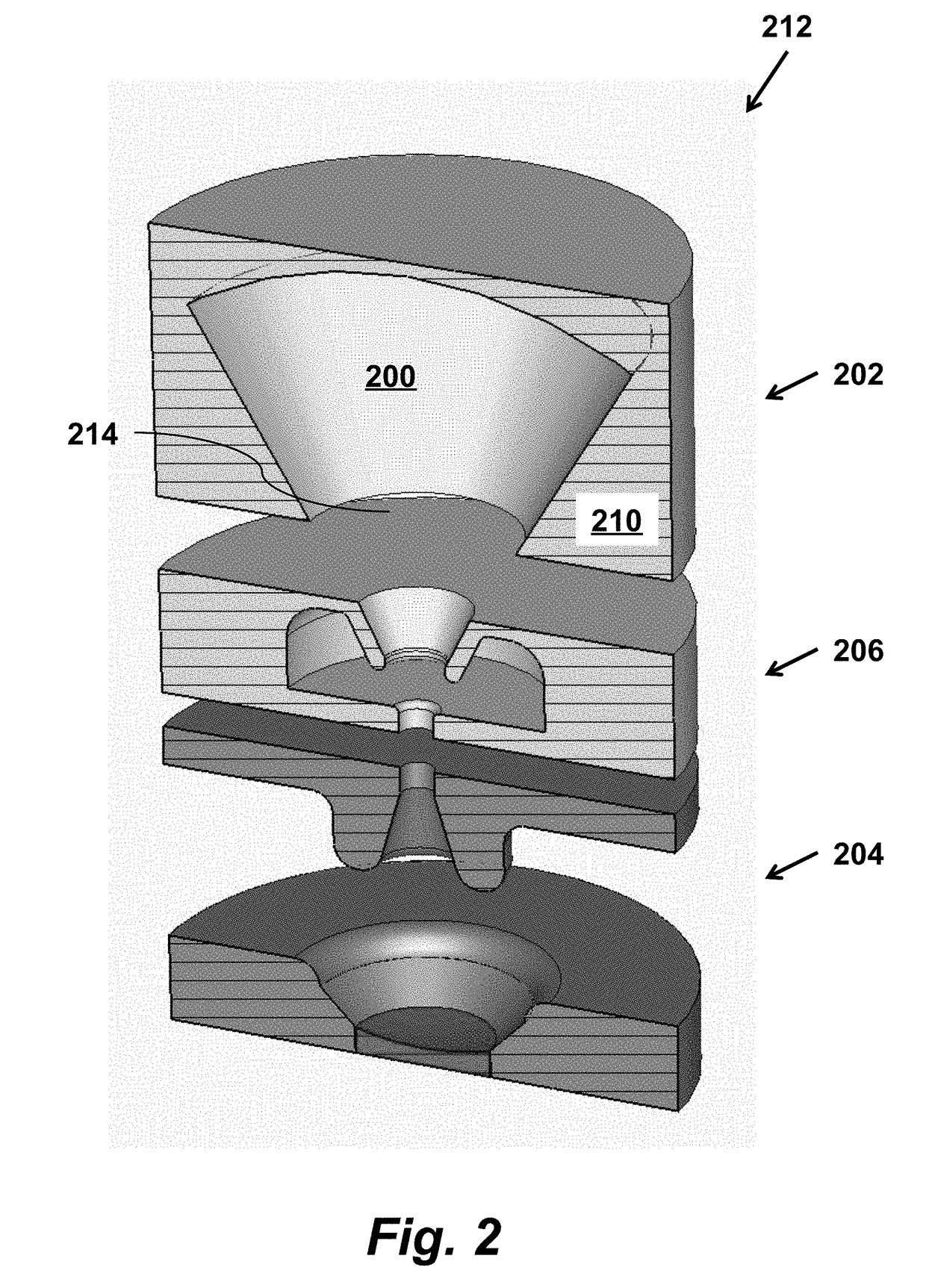
[0043]As shown in FIG. 1, an apparatus for generating high frequency electromagnetic radiation according to an embodiment of the invention includes a whispering gallery mode resonator 100 coupled to an output waveguide 102 through a coupling aperture 104. The resonator has a guiding surface 106 and supports a whispering gallery electromagnetic eigenmode. The apparatus also includes a beam entrance opening 108, solid piece of metallic material 110, and inner part of the whispering gallery mode resonator 112. The apparatus is designed so that a velocity vector-modulated electron beam 114, where each electron in the velocity vector-modulated electron beam 114 is travelling substantially perpendicular to the guiding surface 106, while interacting with the whispering gallery electromagnetic eigenmode in the whispering gallery mode resonator 100, generates high frequency electromagnetic radiation in the output waveguide 102.

[0044]The apparatus functions to generate high frequency electrom...


PUM


Abstract

An apparatus for generating high frequency electromagnetic radiation includes a whispering gallery mode resonator, coupled to an output waveguide through a coupling aperture. The resonator has a guiding surface, and supports a whispering gallery electromagnetic eigenmode. An electron source is configured to generate a velocity vector-modulated electron beam, where each electron in the velocity vector-modulated electron beam travels substantially perpendicular to the guiding surface, while interacting with the whispering gallery electromagnetic eigenmode in the whispering gallery mode resonator, generating high frequency electromagnetic radiation in the output waveguide.

Description

FIELD OF THE INVENTION[0001]This invention relates to vacuum tubes for high power microwave and mm-wave generation. More specifically it relates to phase-locked oscillators and frequency multipliers such as Gyrocons and Trirotrons.BACKGROUND OF THE INVENTION[0002]The mm-wave region of the electromagnetic spectrum (defined herein to mean 30 GHz up to 1 THz) is still unexploited in high-power RF devices, mainly because of the lack of phased-locked sources that are able to provide substantial amount of power. Traditional linear interaction RF sources, such as Klystrons and Traveling Wave Tubes, fail to produce significant power levels at this part of the frequency spectrum. This is because their critical dimensions are small compared to the wavelength, and therefore the amount of beam current that can go through the beam apertures is very limited. There is therefore a need for compact, high power mm-wave sources. These would also enable several additional applications such as basic res...

Claims


Application Information

Patent Timeline
Patent Type & Authority Applications(United States)
IPC IPC(8): H05H9/02H05H7/08H05H7/22
CPCH05H2007/084H05H7/22H05H7/08H05H9/02H01J25/78
Inventor TANTAWI, SAMI G.TOUFEXIS, FILIPPOSFAZIO, MICHAEL V.DOLGASHEV, VALERY A.
Owner THE BOARD OF TRUSTEES OF THE LELAND STANFORD JUNIOR UNIV
Why Eureka
Try Eureka