Effective discharge of exhaust from submerged combustion melters and methods
a technology of submerged combustion melters and exhaust gas, which is applied in the direction of lighting and heating apparatus, furnaces, separation processes, etc., can solve the problems of high pressure, high turbulence and foaming, and rapid melting of feedstock, so as to minimize or eliminate the carryover improve the discharge of exhaust gas, and maximize the mixing of particulate feed materials
- Summary
- Abstract
- Description
- Claims
- Application Information
AI Technical Summary
Benefits of technology
Problems solved by technology
Method used
Image

Examples
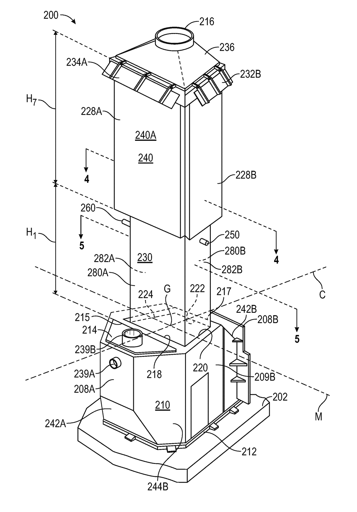
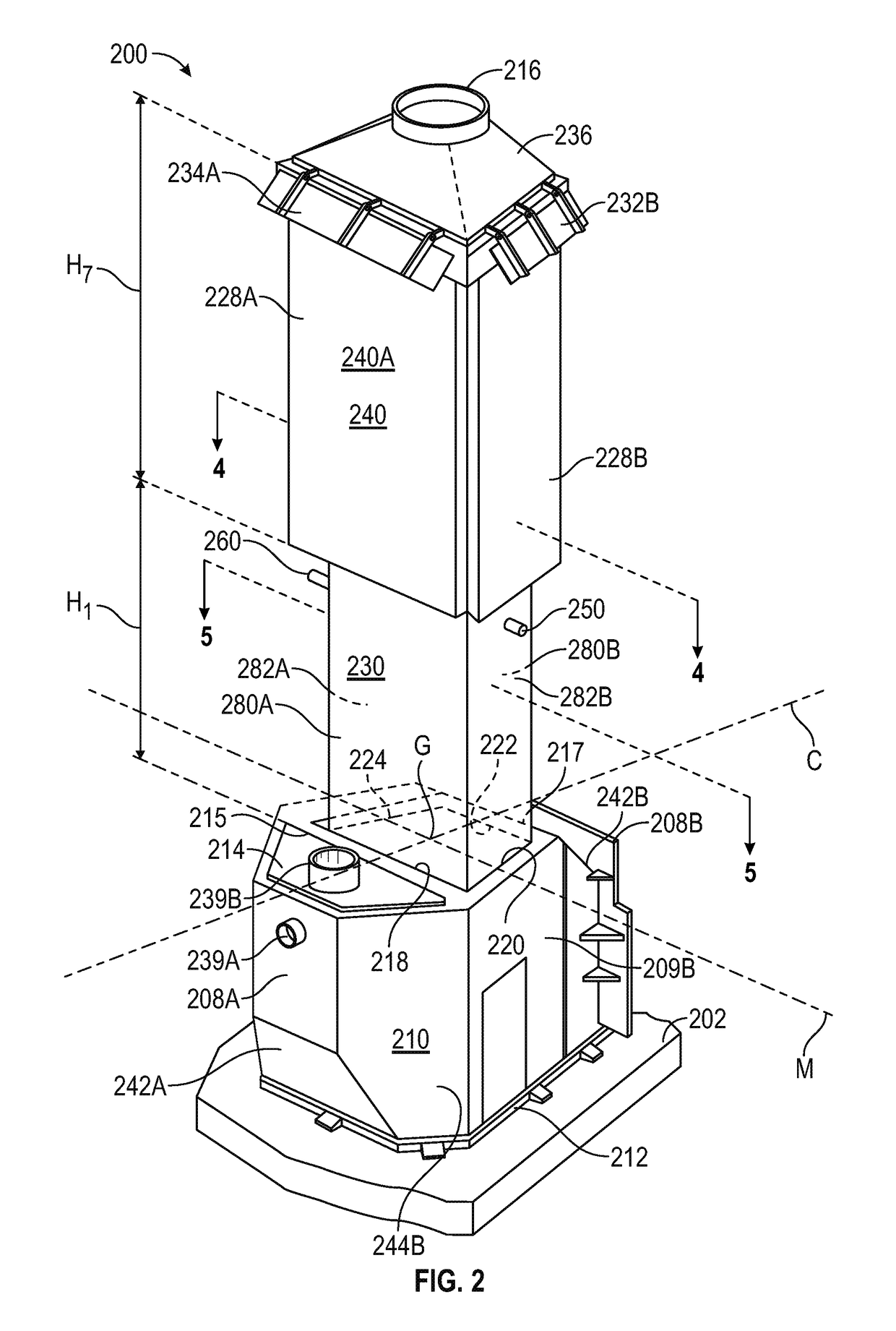
embodiment 200
[0047]An exhaust structure in embodiment 200 is defined by a water-cooled exhaust structure 230 and an air-cooled exhaust structure 240. Water-cooled exhaust structure 230 has a double-trapezoid cross-sectional shape similar to the exhaust opening defined by 218, 220, 222, and 224, although this is not necessary, as other rectilinear two-dimensional shapes (for example triangular, square, rectangle, and the like) or curvilinear two-dimensional shapes (circular, elliptical, arcuate, and the like), or combinations thereof (for example, a hemisphere intersecting a rectangle) may be envisioned. Water-cooled exhaust structure 230 includes a water inlet conduit 250 and a water exit conduit 260 (there may be more than one of each), and is a double-walled structure such as illustrated schematically in the cross-section of FIG. 5. Referring to FIG. 5, front and rear external panels 280A and 280B form with external side panels 282A and 282B an outer trapezoid, with an inner trapezoid formed b...
embodiment 300
[0051]Important features of embodiment 300 include the provision of an angle “α” of the initial portions of the liquid-cooled exhaust structures 326A and 326B that fluidly connect these structures with their respective exhaust openings 315A and 315B. This “exhaust angle” a is configured to assist the liquid-cooled exhaust structure in preventing the ejected material portions of melted material from being propelled out of the exhaust structure as solidified material, and maintain any molten materials contacting the first interior surface molten so that it flows back down the first interior surface back into the melter, and may range from about 20 degrees to about 80 degrees (the angle may be the same or different for 315A and 315B). All individual values and subranges of exhaust angle from about 20 degrees up to about 80 degrees are included herein and disclosed herein; for example, the exhaust angle may range from a lower limit of 17, 20, 25.5, 26, 27, 34.8, 44, 53.5, 62.9, 65, or 7...
PUM
| Property | Measurement | Unit |
|---|---|---|
| exhaust velocity | aaaaa | aaaaa |
| velocity | aaaaa | aaaaa |
| length | aaaaa | aaaaa |
Abstract
Description
Claims
Application Information
 - R&D
- Intellectual Property
- Life Sciences
- Materials
- Tech Scout
- Unparalleled Data Quality
- Higher Quality Content
- 60% Fewer Hallucinations
Browse by: Latest US Patents, China's latest patents, Technical Efficacy Thesaurus, Application Domain, Technology Topic, Popular Technical Reports.
© 2025 PatSnap. All rights reserved.Legal|Privacy policy|Modern Slavery Act Transparency Statement|Sitemap|About US| Contact US: help@patsnap.com