
Capacitor with pressure interrupter

a technology of interrupter and capacitor, which is applied in the direction of capacitors, capacitor housing/encapsulation, electrical apparatus, etc., can solve the problems of affecting the operation of the pressure interrupter, breaking the connection between the tabs and rivets, and difficulty in maintaining the clearance necessary for the pressure interrupter to function

Active Publication Date: 2017-12-28
CORNELL DUBILIER ELECTRONICS
View PDF5 Cites 32 Cited by
  • Summary
  • Abstract
  • Description
  • Claims
  • Application Information

AI Technical Summary

Benefits of technology

The patent text describes a second pressure interrupter mechanism that can be added to a capacitor. This mechanism is designed to break electrical connections when there is pressure on the case, which ensures that the connections are always broken in the same location, regardless of changes in the distance between the plate and the terminals. The technical effect of this design is that it prevents any damage or malfunction caused by the expanding pressure on the capacitor.

Problems solved by technology

Certain capacitors are required to be provided with a pressure interrupter, that is, when pressure builds in the case due to a failure of the capacitor, the case expands, thereby causing a break in the electrical connection between the capacitor element and the terminals mounted on the case.
When pressure builds within the case due to an internal fault, the cover bulges outward, causing the terminals to move away from the rigid plate, thereby breaking the connections between the tabs and the rivets.
For some applications, however, such as mounting the capacitor on a busbar, it may be difficult to maintain the clearance necessary for the pressure interrupter to function.
An increase in the pressure within the housing causes the bottom to flex outward and break the conductor.
Whether a bridge type or bellows type pressure interrupter is provided with the capacitor, mounting brackets, heavy cables and other structural members may restrict expansion of the capacitor cover or housing at a particular installation.

Method used


Image

  • Capacitor with pressure interrupter
  • Capacitor with pressure interrupter
  • Capacitor with pressure interrupter

Examples


case 2

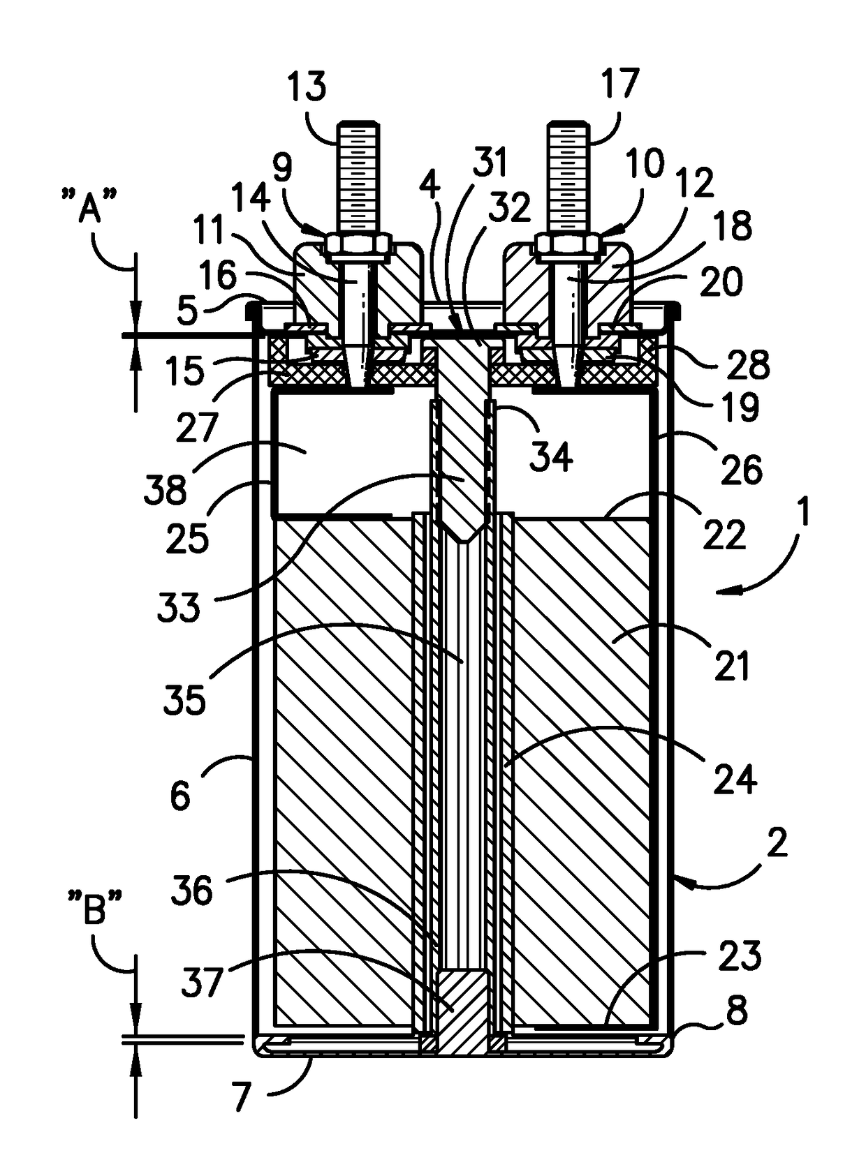
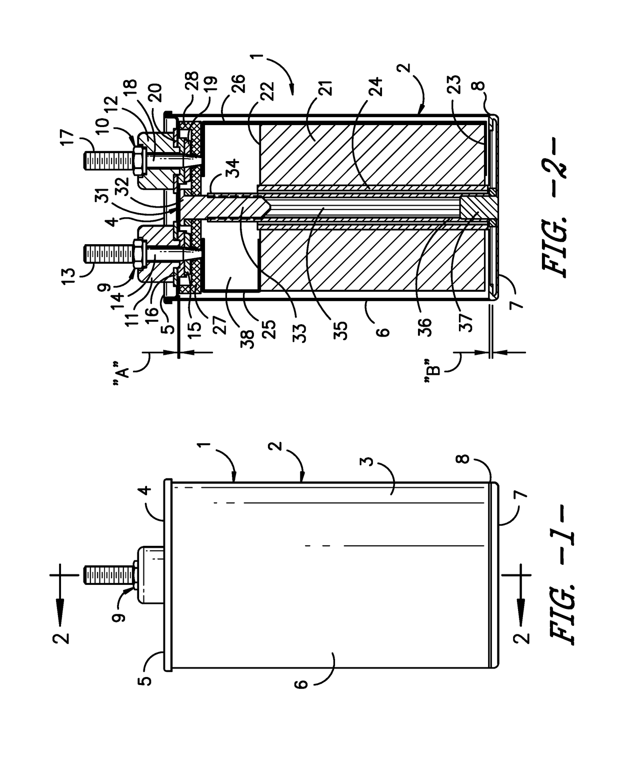
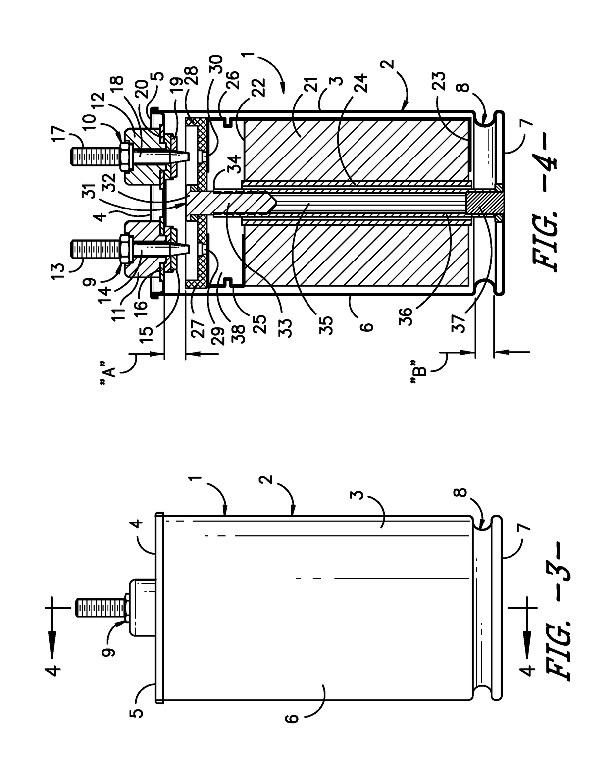
[0039]Case 2 is illustrated as being cylindrical, but may be a rectangular prism or other three-dimensional geometry, or combinations thereof. For example, the case may be in the shape of a rectangular prism, having a rectangular bottom and a rectangular cross-section with planar sides along the sleeve, which transitions to a circular top opening and terminal board. The term “side walls” is intended to include the lateral surface of a cylindrical case.

[0040]Case 2 is made from a material that is substantially impermeable to gases. By way of example, the case may be made out of metal, in particular, steels including cold-rolled steel, mild steel, stainless steel, and other alloys, copper, tantalum, aluminum, titanium, niobium, nickel, iron, and zinc. If the case material is susceptible to corrosion, either internally or externally, the material may be coated, plated or provided with other protective treatment, as is known to those skilled in the art. Alternatively, the case may be ma...


PUM


Abstract

A capacitor is provided with a case having a receptacle with an expandable section that allows the receptacle to extend axially when internal pressure builds within the case as a result of a fault. Terminals are mounted on the cover and electrically connected to the electrodes of a capacitor element through an interrupter plate, via leads. The plate is attached to the section of the case that extends under pressure, whereby the plate is drawn away from the cover, thereby breaking the electrical connections to the terminal. The plate may also work in conjunction with a cover that expands outward in response to internal pressure, to provide a second pressure interrupter mechanism.

Description

[0001]The present invention is directed to a capacitor having a receptacle that expands axially under pressure. An interrupter plate is positioned in the capacitor and attached to the receptacle. The interrupter plate is pulled away from one or more terminals mounted on the cover of the case, when the receptacle expands, thereby breaking the electrical connection to the terminals. The capacitor may be provided with a second interrupter mechanism, which activates when the cover expands outward under pressure away from the plate, thereby breaking the electrical connection to one or more terminals mounted on the cover.BACKGROUND OF THE INVENTION[0002]Certain capacitors are required to be provided with a pressure interrupter, that is, when pressure builds in the case due to a failure of the capacitor, the case expands, thereby causing a break in the electrical connection between the capacitor element and the terminals mounted on the case.[0003]One type of interrupter is the “bridge” typ...

Claims


Application Information

Patent Timeline
IPC IPC(8): H01G2/18H01G2/10
CPCH01G2/18H01G9/08H01G2/103H01G4/14H01G4/32H01G9/12H01G9/151
Inventor CASANOVA, HECTOR ARSENIOBATISTA, RUI MIGUELLOBO, EDWARD MARTINJORISSEN, JR., PAUL MATHEW JAN
Owner CORNELL DUBILIER ELECTRONICS
Features
  • Generate Ideas
  • Intellectual Property
  • Life Sciences
  • Materials
  • Tech Scout
  • Unparalleled Data Quality
  • Higher Quality Content
  • 60% Fewer Hallucinations
Learn More