Telemedical wearable sensing system for management of chronic venous disorders

a technology of chronic venous disorders and wearable sensing, applied in the field of medical sensing and monitoring devices and methods, can solve the problems of never determining the therapeutic pressure dose, unoptimized treatment parameters, etc., and achieve the goal of optimizing the overall treatment of a particular patient, reducing treatment times, and achieving objective quality

Inactive Publication Date: 2018-01-04
RGT UNIV OF CALIFORNIA
View PDF0 Cites 15 Cited by
  • Summary
  • Abstract
  • Description
  • Claims
  • Application Information

AI Technical Summary

Benefits of technology

[0029]The response of the patient to the compression treatments over time can also be evaluated. The needed changes in pressure treatment can be made quickly to allow the overall treatment of a particular patient to be optimized. If a wearable device is available to the clinical staff each time a compression bandage therapy is performed, the bandages can be maneuvered to keep interface pressure within a certain therapeutic range determined by the physician and this will translate to objective quality assurance, decreased treatment times and patient tailored treatments.
[0030]Pressure excesses at locations along the appendage can also be identified to avoid the occurrence of pressure damage over bony or tendinous prominences of the leg, for example. Likewise, the system can verify the actual pressures at different locations on the appendage in cases where graduated compression up the leg is desired.
[0031]The system can also determine if the compression bandages or other device was applied properly and can identify any changes in applied compression that may take place over time due to material fatigue or anatomical changes etc. Traveling to and from clinical visits remains an obstacle for many patients with bulky compression bandages since such patients are often not fully ambulatory. Accurate status monitoring by the system of the compression device remotely can also eliminate the need for frequent clinical visits, so the patient can avoid taking time off from work and minimize wage loss, cost of travel and loss of time. Moreover, this will lead to a better quality of life given that such a treatment modality can be performed at the comfort of the home of the patient on a consistent basis.

Problems solved by technology

A therapeutic pressure dose is never characterized or determined and treatment parameters are not optimized in these therapies.

Method used


Image

  • Telemedical wearable sensing system for management of chronic venous disorders
  • Telemedical wearable sensing system for management of chronic venous disorders
  • Telemedical wearable sensing system for management of chronic venous disorders

Examples


example 1

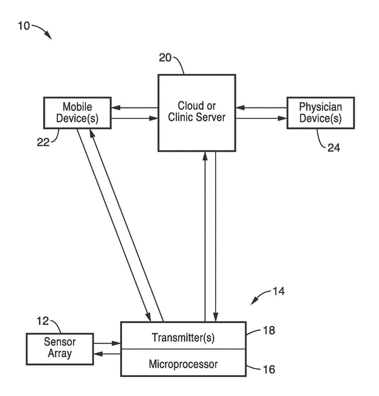
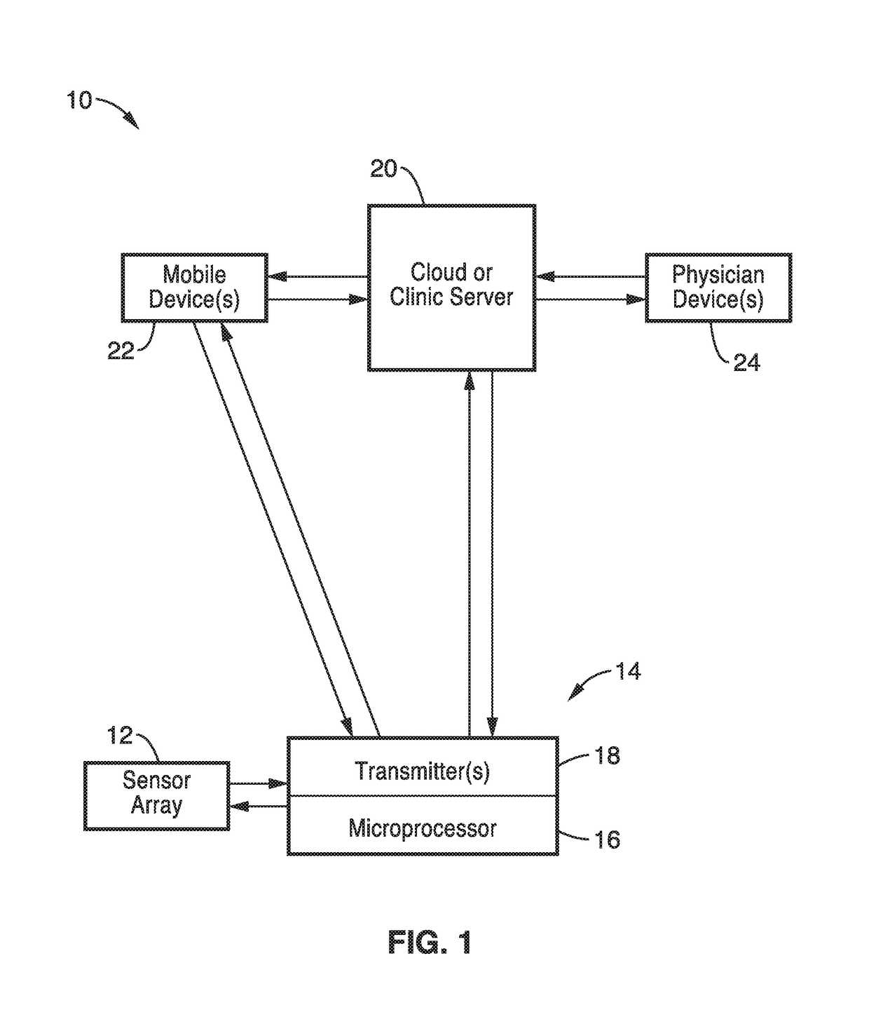
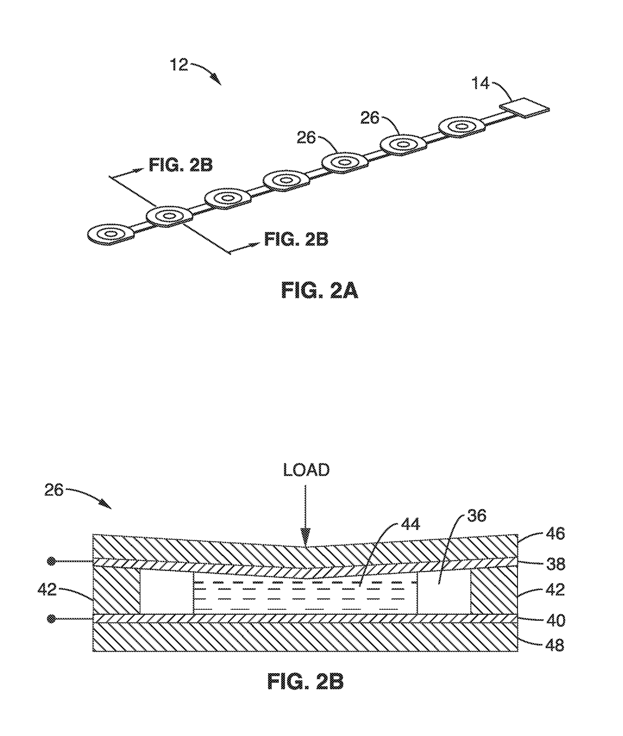
[0103]In order to demonstrate the technology, a system was designed based on a single ionic gel-based pressure sensor of the design depicted schematically in FIG. 2B. The sensor used a nanoliter ionic gel droplet sandwiched between the top and bottom flexible ITO coated polyethylene terephthalate (PET) membranes. A separation layer supports the spacing between the two sensing membranes and on one side of the membrane, a 10 μm-high, 200 μm-diameter micropillar perform as the anchor for the ionic gel. Upon the ionic gel-electrode contact, electrical double layer (EDL) capacitance has formed. Under external mechanical loads, the polymer membranes deform, leading to the circumferential expansion of the ionic gel droplet. The variation in the ionic gel and electrode contact area will lead to a proportional change in the interfacial capacitance. To facilitate pressure distribution measurement, a 1 by 8 sensing array with 3 cm interval was designed and fabricated to achieve a pressure dist...

example 2

[0106]In order to further demonstrate the technology, a low-power wireless interface for pressure data acquisition and processing of the microfluidic sensing array was constructed. The system provided an analog front, a microcontroller and a Bluetooth transmission module as well as graphic user interface. Analog-front component converted sensor impedance into a voltage signal. The ultra-low-power MSP430 microcontroller allowed all digital processing, including data acquisition, processing and serial communication, from which the Bluetooth transmission module can be used to achieve wireless communication with PC, tablet, cellular phone user interface or any other mobile platform.

[0107]The analog front was devised to interrogate each capacitive sensing element of the microfluidic sensing array consecutively and the collective interface pressure data was acquired into an electronic circuitry. The interfacial EDL capacitance was found to offer both stable high unit-area capacitance and ...


PUM

PropertyMeasurementUnit
interface pressureaaaaaaaaaa
pressuresaaaaaaaaaa
pressuresaaaaaaaaaa

Abstract

A telemedical interface pressure monitoring system is provided for intermittent or continuous monitoring of the pressure that occurs at the interface between the body and a support surface such as with a compression device, cast or resting surface. The system simultaneously measures interface pressure at multiple compression positions as well as provide real-time measurement data to both patients and clinicians. The system uses an array of one or more sensors and a data collection and transmission node with a microprocessor and transmitter/receiver that transmits the sensor data to a receiver such as a mobile device or cloud or clinic server for remote display, evaluation and automatic recording. Remote receivers can also control compression devices associated with the node.

Description

CROSS-REFERENCE TO RELATED APPLICATIONS[0001]This application is a 35 U.S.C. §111(a) continuation of PCT international application number PCT / US2015 / 059320 filed on Nov. 5, 2015, incorporated herein by reference in its entirety, which claims priority to, and the benefit of, U.S. provisional patent application Ser. No. 62 / 075,731 filed on Nov. 5, 2014, incorporated herein by reference in its entirety. Priority is claimed to each of the foregoing applications.[0002]The above-referenced PCT international application was published as PCT International Publication No. WO 2016 / 073777 on May 12, 2016, which publication is incorporated herein by reference in its entirety.STATEMENT REGARDING FEDERALLY SPONSORED RESEARCH OR DEVELOPMENT[0003]This invention was made with Government support under 1307831, awarded by the National Science Foundation. The Government has certain rights in the invention.INCORPORATION-BY-REFERENCE OF COMPUTER PROGRAM APPENDIX[0004]Appendix A referenced herein is a com...

Claims


Application Information

Patent Timeline
Patent Type & Authority Applications(United States)
IPC IPC(8): A61F13/06A61B5/0205G01L19/00A61F13/10G06F19/00A61F13/00
CPCA61F13/06A61F13/10G06F19/3418A61B5/02055G01L19/0092G01L2019/0053A61H2230/06A61H2201/5043A61H2201/5058A61H2201/5061A61H2201/5082A61H2209/00A61F2013/0094A61B5/4836A61H9/0078G01L9/0072
Inventor PAN, TINGRUILI, RUYACHI, YUNG-WEI
Owner RGT UNIV OF CALIFORNIA
Why Eureka
Try Eureka