Sensorized roller

a technology of roller bearings and sensors, applied in mechanical equipment, instruments, force/torque/work measurement apparatus, etc., can solve the problem of limiting the rotation of the housing within the bore, and achieve the effect of convenient mounting and dismounting, accurate positioning, and convenient transmission of signals

Active Publication Date: 2018-01-04
AB SKF
View PDF2 Cites 8 Cited by
  • Summary
  • Abstract
  • Description
  • Claims
  • Application Information

AI Technical Summary

Benefits of technology

[0007]The measuring device and electronics are thus protected against contaminants such as lubricant and moisture by the housing and by the first and second sealing elements that seal the bore at both axial ends. Friction between the sealing elements and the bore surface also limits rotation of the housing within the bore. Furthermore, the resilient first and second sealing elements take up deformations of the roller bore, to prevent the housing from coming into contact with the bore. The housing is made from a rigid material such as plastic which is sufficiently stiff in radial direction to prevent contact between the bore and the housing along the full axial length of the housing.
[0008]The housing, measuring device and electronics form a sensor unit that can be easily mounted to and dismounted from the roller bore. The electronics of the sensor unit comprise at least a processor and an antenna. Preferably, the sensor unit housing is fully contained within exterior dimensions of the roller.
[0009]In a preferred embodiment, the sensor unit is configured such that the components housed therein can be replaced or serviced. The housing may comprise two semi-cylindrical housing portions which are joined by means of first and second end caps that fit over first and second axial ends of the two housing portions. In one example, the first and second axial ends of the housing portions are provided with an external thread and the first and second end caps are provided with a cooperating internal thread. To prevent unscrewing, each end cap may be provided with a retaining lip that engages with a corresponding notch in the housing body. Alternatively, the housing body may be provided with a lip that engages in a notch provided in the end cap.
[0010]The housing of the sensor unit enables the measuring device to be accurately located within the roller bore. The housing also locates the electronics of the sensor unit, which is especially important with regard to the antenna for transmitting the processed deformation signal. Suitably, the antenna is located as close as possible to an axially outer end of the roller, to facilitate transmission of the signal.

Problems solved by technology

Friction between the sealing elements and the bore surface also limits rotation of the housing within the bore.

Method used


Image

  • Sensorized roller
  • Sensorized roller
  • Sensorized roller

Examples


Embodiment Construction

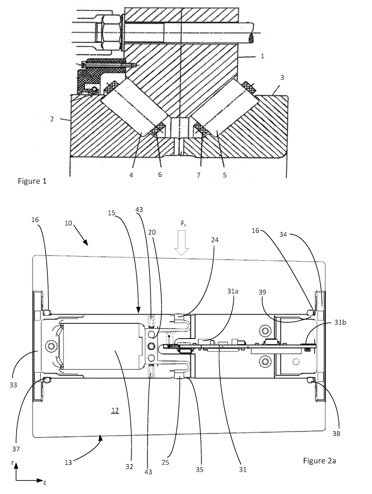
[0024]An example of a bearing that is suitable for supporting the main shaft of a wind turbine is shown in FIG. 1. The bearing must withstand high axial loads as well as radial loads and is executed as a double-row tapered roller bearing. The bearing comprises an outer ring 1 provided with conically shaped first and second outer raceways for a first set 4 and a second set 5 of tapered rollers. The bearing further comprises first and second inner rings 2, 3 which are respectively provided with conically shaped first and second inner raceways for the first and second roller sets 4, 5. In addition, a first cage 6 and a second cage 7 are provided for retaining the rollers of the first and second roller sets respectively. Typically, the cages are formed from segments that abut each other in circumferential direction.

[0025]To provide the necessary stiffness and ensure a long service life, the bearing is preloaded. The axial position of the inner rings 2, 3 relative to the outer ring 1 is ...


PUM


Abstract

The present invention resides in a sensorized roller of a roller bearing. The sensorized roller includes a roller bore that accommodates a measuring device for measuring deformation of the roller bore and electronics for processing a deformation signal from the measuring device and wirelessly transmitting the processed deformation signal to an external receiver. According to the invention, the measuring device and electronics are mounted in a rigid housing that is shaped to fit within the roller bore. A radially outer surface of the housing includes at least one aperture associated with the measuring device. Furthermore, the rigid housing is resiliently mounted to the roller bore via first and second sealing elements that enclose a radial gap between a radially inner surface of the roller bore and a radially outer surface of the housing.

Description

CROSS REFERENCE TO RELATED APPLICATIONS[0001]This application claims priority to German patent application no. 102016211779.3 filed on Jun. 29, 2016, the contents of which are fully incorporated herein by reference.FIELD OF THE INVENTION[0002]The present invention relates to the field of load detection in roller bearings and is more particularly directed to a bearing roller with a hollow bore in which one or more sensors are provided for measuring deformation of the roller bore.BACKGROUND OF THE INVENTION[0003]An example of a bearing roller of this kind is known from U.S. Pat. No. 9,127,649. The roller is equipped with a sensor that detects a physical state of the bearing roller, which sensor is attached to an inner surface of the roller bore, which defines a cavity. A signal from the sensor is received by a processing portion, which processes and transmits the detection signal to a receiver outside of the bearing. The processing portion is provided on a substrate accommodated withi...

Claims


Application Information

Patent Timeline
Patent Type & Authority Applications(United States)
IPC IPC(8): G01B21/32F16C33/36F16C19/38F16C41/00
CPCG01B21/32F16C19/386F16C2233/00F16C41/008F16C2360/31F16C33/366F16C19/184F16C19/522F16C33/34F16C41/00F16C2240/18F16C2300/14F16C19/361F16C41/002F16C2240/12G01L5/0019G01L5/0028G01M5/0041
Inventor VAN DER HAM, ANDREAS CLEMENSDEN HAAK, NICOLAAS SIMON WILLEMDOP, GERRIT-JANQIU, FENGVAN DIERMEN, JEROEN
Owner AB SKF
Why Eureka
Try Eureka