Focusing apparatus, focusing method, and pattern inspection method

a technology of focusing apparatus and focusing method, which is applied in the direction of semiconductor/solid-state device testing/measurement, instruments, television systems, etc., can solve the problems of reducing the yield of lsi manufacturing, difficult to accurately focus, and requiring a tremendous amount of manufacturing cos

Active Publication Date: 2018-01-04
NUFLARE TECH INC
View PDF0 Cites 6 Cited by
  • Summary
  • Abstract
  • Description
  • Claims
  • Application Information

AI Technical Summary

Problems solved by technology

Meanwhile, the LSI manufacturing requires a tremendous amount of manufacturing cost, therefore it is crucial to improve its yield.
One of major factors that decrease the yield of the LSI manufacturing is due to pattern defects on the mask used for exposing and transfer printing an ultrafine pattern onto a semiconduct

Method used


Image

  • Focusing apparatus, focusing method, and pattern inspection method
  • Focusing apparatus, focusing method, and pattern inspection method
  • Focusing apparatus, focusing method, and pattern inspection method

Examples


first embodiment

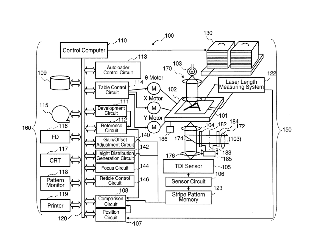
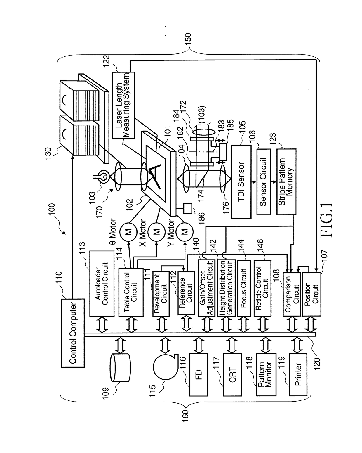
[0023]FIG. 1 illustrates a configuration of a pattern inspection apparatus according to a first embodiment. As shown in FIG. 1, an inspection apparatus 100 that inspects defects of a pattern formed on a mask substrate 101 (example of inspection substrate) includes an optical image acquisition unit 150 and a control system circuit 160 (control circuit).

[0024]The optical image acquisition unit 150 includes a light source 103, a transmission illumination optical system 170, an XYθ table 102 arranged movably, an objective lens 104, a beam splitter 174, a reflection illumination optical system 172, an image forming optical system 176, reticles 182 and 184, a reticle drive mechanism 185, a TDI (Time Delay Integration) sensor 105, a sensor circuit 106, a stripe pattern memory 123, and a laser length measuring system 122. On the XYθ table 102, there is placed a mask substrate 101 (example of inspection substrate) transmitted from a cassette 300. The mask substrate 101 is, for example, an ex...


PUM


Abstract

A focusing apparatus includes a first reticle, arranged at the front side of a conjugate position of a TDI sensor; a second reticle, arranged at the back side of the conjugate position; an equalizing circuit to perform gray scale value equalization by using a gray scale value output by the TDI sensor which received the pattern image by illumination light not passing through the first and second reticles; and a distance change/move amount calculation circuit to calculate, in a state where the gray scale value equalization has been performed, a distance change/move amount of a relative distance, for focusing the pattern image of the substrate, between the substrate and the conjugate position of the TDI sensor by using a first derivative value of a gray scale value output by the TDI sensor which received the pattern image by the reflection illumination light having passed through the first and second reticles.

Description

CROSS-REFERENCE TO RELATED APPLICATION[0001]This application is based upon and claims the benefit of priority from the prior Japanese Patent Application No. 2016-131993 filed on Jul. 1, 2016 in Japan, the entire contents of which are incorporated herein by reference.BACKGROUND OF THE INVENTIONField of the Invention[0002]Embodiments of the present invention relate generally to a focusing apparatus, focusing method, and pattern inspection method. For example, embodiments of the present invention relate to a pattern inspection technique for inspecting pattern defects of an object serving as a target workpiece or “sample” used in manufacturing semiconductor devices, and to an inspection apparatus for inspecting an exposure mask substrate used in manufacturing semiconductor elements or liquid crystal displays (LCDs).Description of Related Art[0003]In recent years, with the advance of high integration and large capacity of large-scale integration (LSI) circuits, the line width (critical d...

Claims


Application Information

Patent Timeline
IPC IPC(8): G01N21/956H04N5/232H04N5/235
CPCG01N21/95607G01N2021/95676H04N5/23212H04N5/2352H04N23/67H04N25/71G03F1/44G03F7/2063G03F7/70141G03F7/70641H01L22/12H01L22/30H04N23/72
Inventor OTAKI, TOSHIAKIOGAWA, RIKI
Owner NUFLARE TECH INC
Why Eureka
Try Eureka