
Reflective illuminating optical system

Inactive Publication Date: 2007-02-06
LG ELECTRONICS INC
View PDF9 Cites 6 Cited by
  • Summary
  • Abstract
  • Description
  • Claims
  • Application Information

AI Technical Summary

Benefits of technology

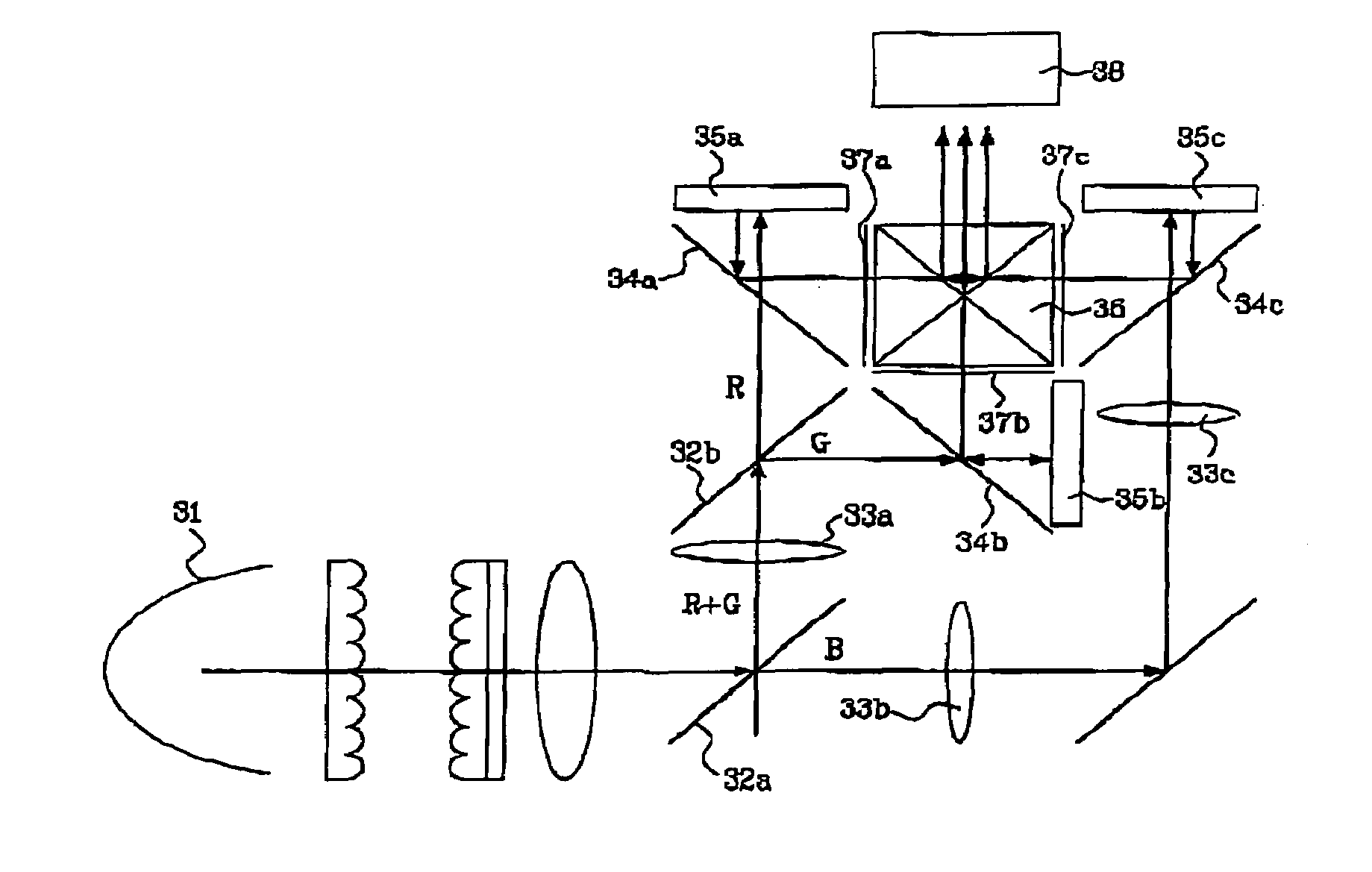
[0055]Accordingly, one object of the present invention is to solve the foregoing problems by providing a reflective illuminating optical system, in which R, G, and B signals reflected by an LCoS panel of a projection system do not pass through wire grid type PBSs (Polarized Beam Splitters) but are reflected by the PBSs and eventually are incident on a projection leans, whereby astigmatism is suppressed and illuminating efficiency is improved.
[0057]To increase contrast effects, first, second, and third polarization plates for polarizing the R, G, and B lights are inserted in between the X-prism and the first, second, and third wire grid type PBSs.

Problems solved by technology

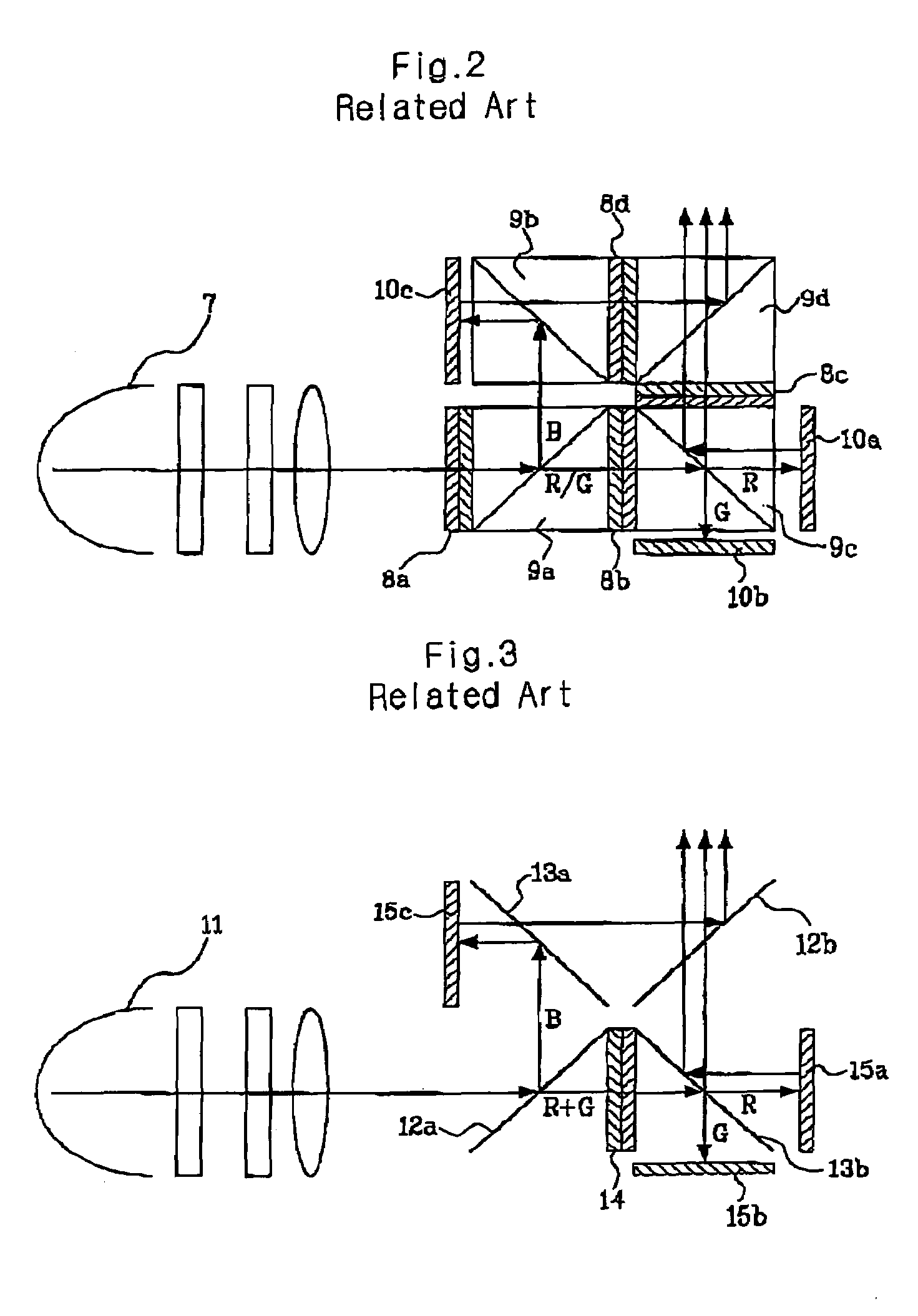
However, the illuminating system of FIG. 2 includes four color selectors and four PBSs, so it is not as cost-effective as expected.
Although the wire grid type PBS-based illuminating system successfully solved the photoelasticity and cost problems and improves illuminating efficiency, it caused astigmatism.
Therefore, when the reflected light from the LCoS panel passes through the wire grid type PBS, astigmatism gets much worse.
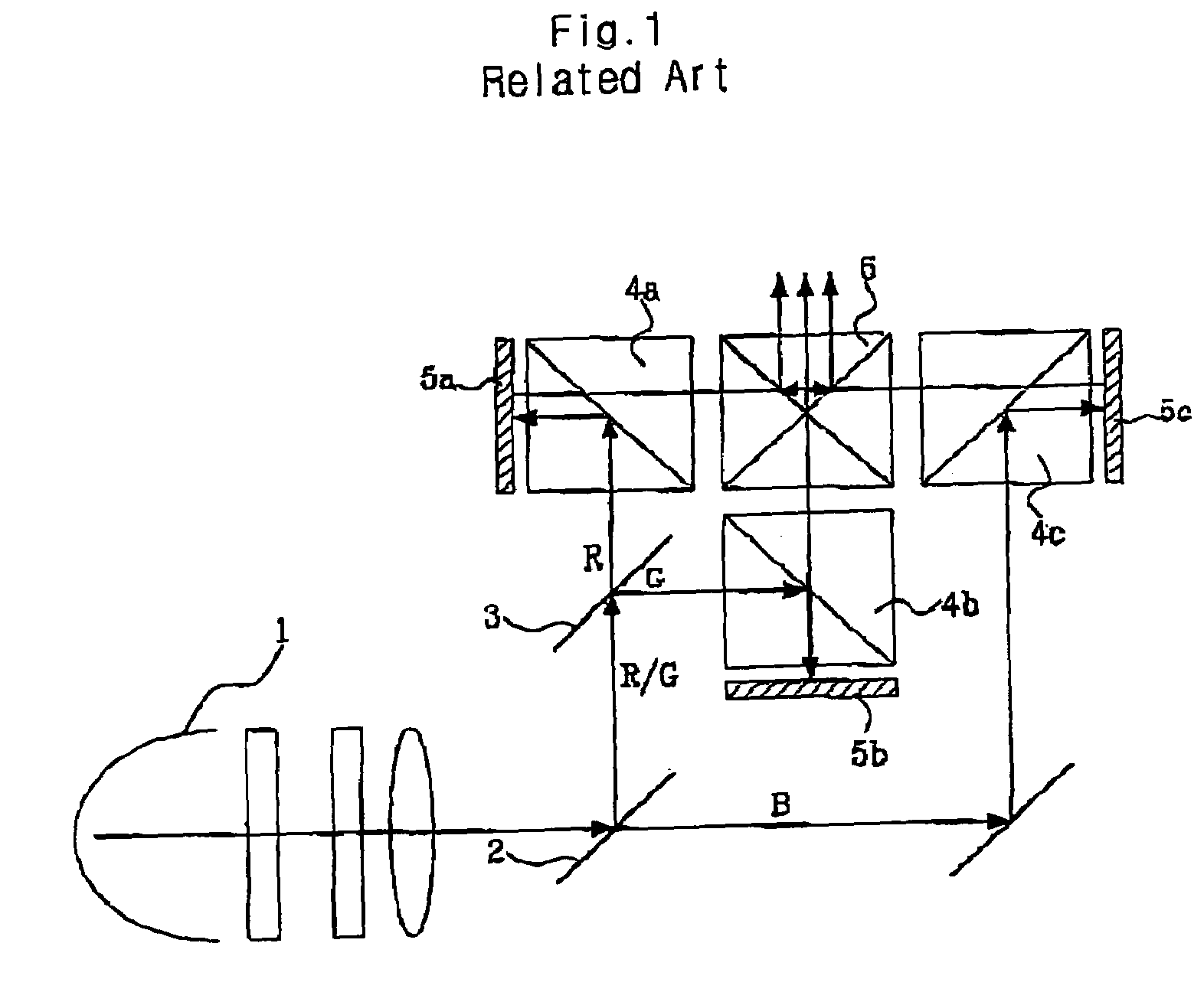
First of all, the 3-step structure for the optical path in the reflective illuminating system with 3 PBSs of FIG. 1 increases the depth of the system and requires too many elements.
Although the reflective illuminating system in color quad system of FIG. 2 simplified the entire structure, it still includes four color selectors and PBSs, resulting in the high price.
However, when the light passes through the wire grid type PBS, astigmatism occurs.
However, when the wire grid type PBS to be inserted is too thin, the PBS itself gets bent.
Also, arraying the PBSs in different directions is not much effective for canceling astigmatism but creates circular shaped spots in large sizes.
Further, because the angle between two PBSs is too large, it is impossible to construct the illuminating system overall.

Method used


Image

  • Reflective illuminating optical system
  • Reflective illuminating optical system
  • Reflective illuminating optical system

Examples


Embodiment Construction

[0072]The following detailed description will present a reflective illuminating optical system according to a preferred embodiment of the invention in reference to the accompanying drawings.

[0073]FIG. 9 is a schematic diagram of a reflective illuminating optical system according to the present invention.

[0074]The present invention is related to a projection display device based on a reflective panel LCoS (Liquid Crystal on Silicon) for example. A new 3-panel reflective illuminating system according to the present invention employs wire grid type PBSs and improves performances, and can be manufactured at low cost.

[0075]In the reflective illuminating optical system of the invention all R, G, and B lights reflected from the LCoS panel do not pass through the wire grid type PBS but are reflected therefrom. As a result, no astigmatism occurs.

[0076]The above result is obtained by employing a polarization film functioning as the wire grid type PBS (i.e. the polarization film performs P / S s...


PUM


Abstract

A reflective illuminating optical system on silicon, more particularly, to an illuminating optical system is provided, in which R, G, and B signals reflected from a LCoS panel (Liquid Crystal on Silicon panel) in a projection system do not pass through wire grid type PBSs (Polarized Beam Splitters) but are reflected by the wire grid type PBSs (Polarized Beam Splitters) so that astigmatism is suppressed and illuminating efficiency is improved.

Description

BACKGROUND OF THE INVENTION[0001]1. Field of the Invention[0002]The present invention relates in general to a reflective illuminating optical system, more particularly, to a reflective illuminating optical system in which R, G, and B signals are reflected by wire grid type PBS (Polarized Beam Splitters) and incident on a projection lens, thereby suppressing astigmatism and improving illuminating efficiency.[0003]2. Discussion of the Background Art[0004]Display devices are becoming slimmer, lighter and have a large screen. Especially, a large screen display device is an ongoing subject in current display technologies. Projection TVs are typical examples of the large screen display device.[0005]Projection TVs are largely classified into CRT (Cathode Ray Tube) projection TVs and LCD (Liquid Crystal Display) projection TVs. The LCD projection TV consists of a transmissive LCD-based system or reflective LCoS (Liquid Crystal on Silicon)-based system.[0006]Particularly, the reflective LCoS...

Claims


Application Information

Patent Timeline
IPC IPC(8): G03B21/14G03B21/28G02B27/18G03B21/00H04N5/74H04N9/31
CPCH04N9/3197H04N9/3105H04N5/74
Inventor KANG, HO JOONG
Owner LG ELECTRONICS INC
Learn More