Display device and method for controlling peak luminance of the same

Active Publication Date: 2018-01-04
SAMSUNG DISPLAY CO LTD
View PDF2 Cites 5 Cited by
  • Summary
  • Abstract
  • Description
  • Claims
  • Application Information

AI Technical Summary

Benefits of technology

[0043]Therefore, the display device according to example embodiments may determine whether the peak image or not every frame and adaptively increase the peak luminance with respect to the peak image that has high contrast and low load, so that the visibility, reality and immersion of the image may be improved. Further, the peak luminance may be controlled by an adaptive image data conversion based on

Problems solved by technology

However, the conventional PLC driving method determines the peak luminance without considering environments such as contrast

Method used


Image

  • Display device and method for controlling peak luminance of the same
  • Display device and method for controlling peak luminance of the same
  • Display device and method for controlling peak luminance of the same

Examples


Embodiment Construction

[0072]Exemplary embodiments will be described more fully hereinafter with reference to the accompanying drawings, in which various embodiments are shown.

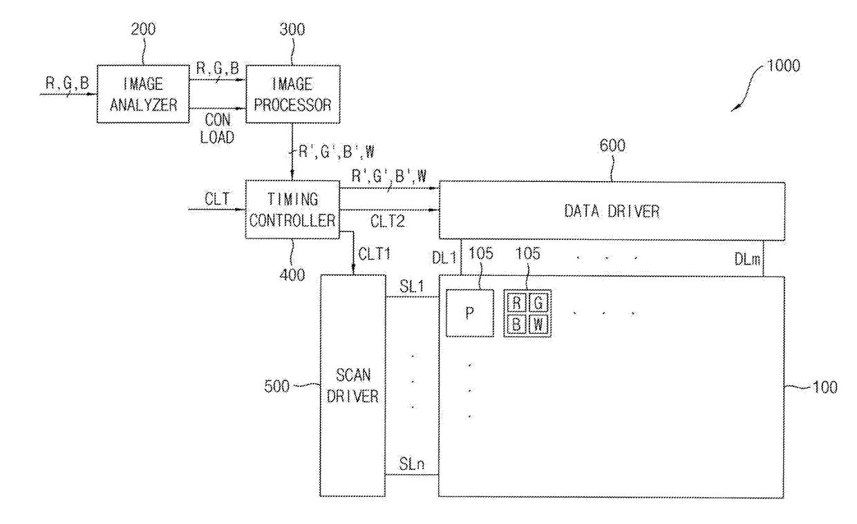
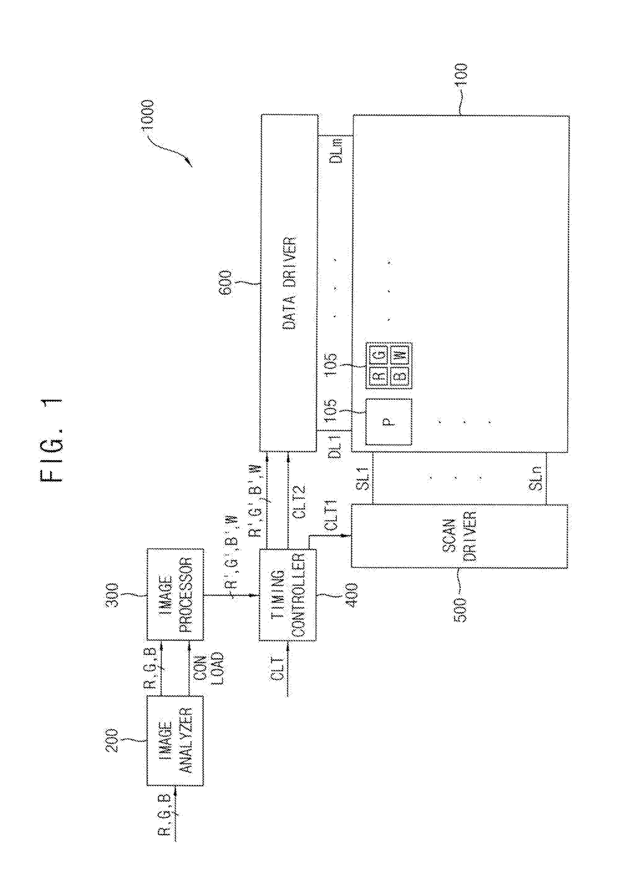
[0073]FIG. 1 is a block diagram of a display device according to example embodiments.

[0074]Referring to FIG. 1, the display device 1000 may include a display panel 100, an image analyzer 200, an image processor 300, a timing controller 400, a scan driver 500, and a data driver 600.

[0075]In one embodiment, the display device 1000 may be implemented as an organic light emitting display device or a liquid crystal display device. Since these are examples, the display device 1000 is not limited thereto.

[0076]The display panel 100 may display images. The display panel 100 may include a plurality of scan lines SL1 through SLn and a plurality of data lines DL1 through DLm. The display panel 100 may also include the pixels P connected to the scan lines SL1 through SLn and the data lines DL1 through DLm. For example, the pixels P may be arran...


PUM


Abstract

A display device according to example embodiments includes an image analyzer configured to calculate contrast and load of an image of a frame based on R, G, and B image data input corresponding to the frame, an image processor configured to control a peak control coefficient applied to W image data to adaptively control peak luminance based on the contrast and the load, and to respectively generate R′, G′, and B′ image data by subtracting a product of the W image data and the peak control coefficient from each of the R, G, and B image data, a display panel including a plurality of pixels, a data driver configured to generate a data signal based on the R′, G′, B, and W image data, and to provide the data signal to the display panel, and a scan driver configured to provide a scan signal to the display panel.

Description

CROSS REFERENCE TO RELATED APPLICATION[0001]This application claims priority to and the benefit of Korean Patent Application No. 10-2016-0081865, filed on Jun. 29, 2016 in the Korean Intellectual Property Office (KIPO), the disclosure of which is hereby incorporated by reference herein in its entirety.BACKGROUND1. Field[0002]Example embodiments of the inventive concept relate to electronic devices. More particularly, example embodiments of the inventive concept relate to display devices and methods for controlling peak luminance of the same.2. Discussion of Related Art[0003]Organic light emitting diode (OLED) displays can display information such as images and characters by emitting light generated from an organic layer. This light is generated in the organic layer via the combination of holes supplied from an anode and electrons supplied from a cathode. OLED displays have advantages over traditional displays such as low power consumption, wide viewing angles, fast response times, s...

Claims


Application Information

Patent Timeline
IPC IPC(8): G09G3/3291G09G3/20G09G3/3266
CPCG09G3/3291G09G3/3266G09G3/2007G09G2300/0452G09G2310/08G09G2320/0646G09G2320/0233G09G3/3233G09G2320/041G09G2320/066G09G2330/021G09G2340/06G09G2360/144G09G2360/16G09G3/20G09G3/36G09G3/3208
Inventor PARK, SEUNG-HOLEE
Owner SAMSUNG DISPLAY CO LTD
Why Eureka
Try Eureka