Cutter holder with vibration resistant structure

a technology of vibration resistance and cutter holder, which is applied in the field of cutter holder, can solve the problems of easy vibration of cutter holder, low processing quality, and conventional cutter holder vibrations during machining, so as to avoid negative influence and achieve high-quality machining

Inactive Publication Date: 2018-01-11
CHEN CHING TING
View PDF23 Cites 12 Cited by
  • Summary
  • Abstract
  • Description
  • Claims
  • Application Information

AI Technical Summary

Benefits of technology

[0004]The main objective of the present invention is to provide a vibration resistant cutter holder that can avoid the negative influence brought about by vibrations during machining and perform high-quality machining.
[0005]The cutter holder comprises a body and a damping assembly. The damping assembly is contained inside the body. The damping assembly has a central damping pole and six auxiliary damping poles. The six auxiliary damping poles are arranged around the central damping pole. The body has a specific weight. The central damping pole has a specific weight larger than the specific weight of the body. Each one of the six auxiliary damping poles has a specific weight larger than the specific weight of the body as well. The damping assembly is utilized to reduce vibrations caused by machining.

Problems solved by technology

Vibrations of a cutter holder easily occur as the rigidness of the cutter holder is insufficient, the frequency of the reaction force and the resonance frequency of the cutter holder are similar, or the cutter holder is suddenly encountered with an intense reaction force.
Generally, the conventional cutter holder inevitably generates vibrations during machining.
The vibrations have little influence on processing quality when utilizing cutter holders with shorter lengths.
However, for cutter holders with longer lengths, the vibrations decrease the efficiency of machining, generate noise, and form obvious marks of machining and a rough surface on a work piece.
The conventional cutter holder lacks vibration resistant structures and consequently brings about negative influence on the quality of the work piece.

Method used


Image

  • Cutter holder with vibration resistant structure
  • Cutter holder with vibration resistant structure
  • Cutter holder with vibration resistant structure

Examples


Embodiment Construction

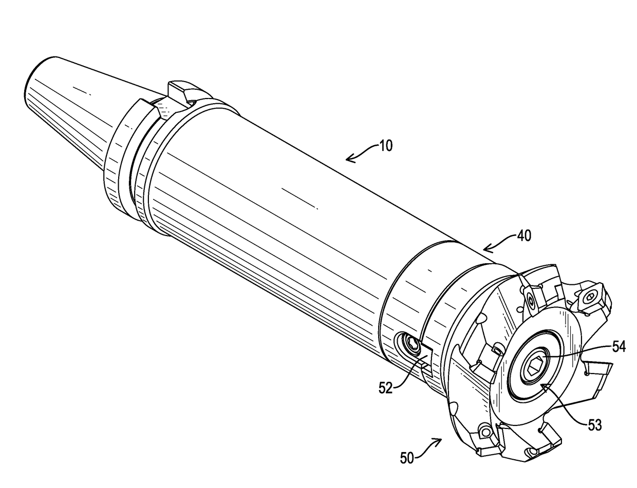
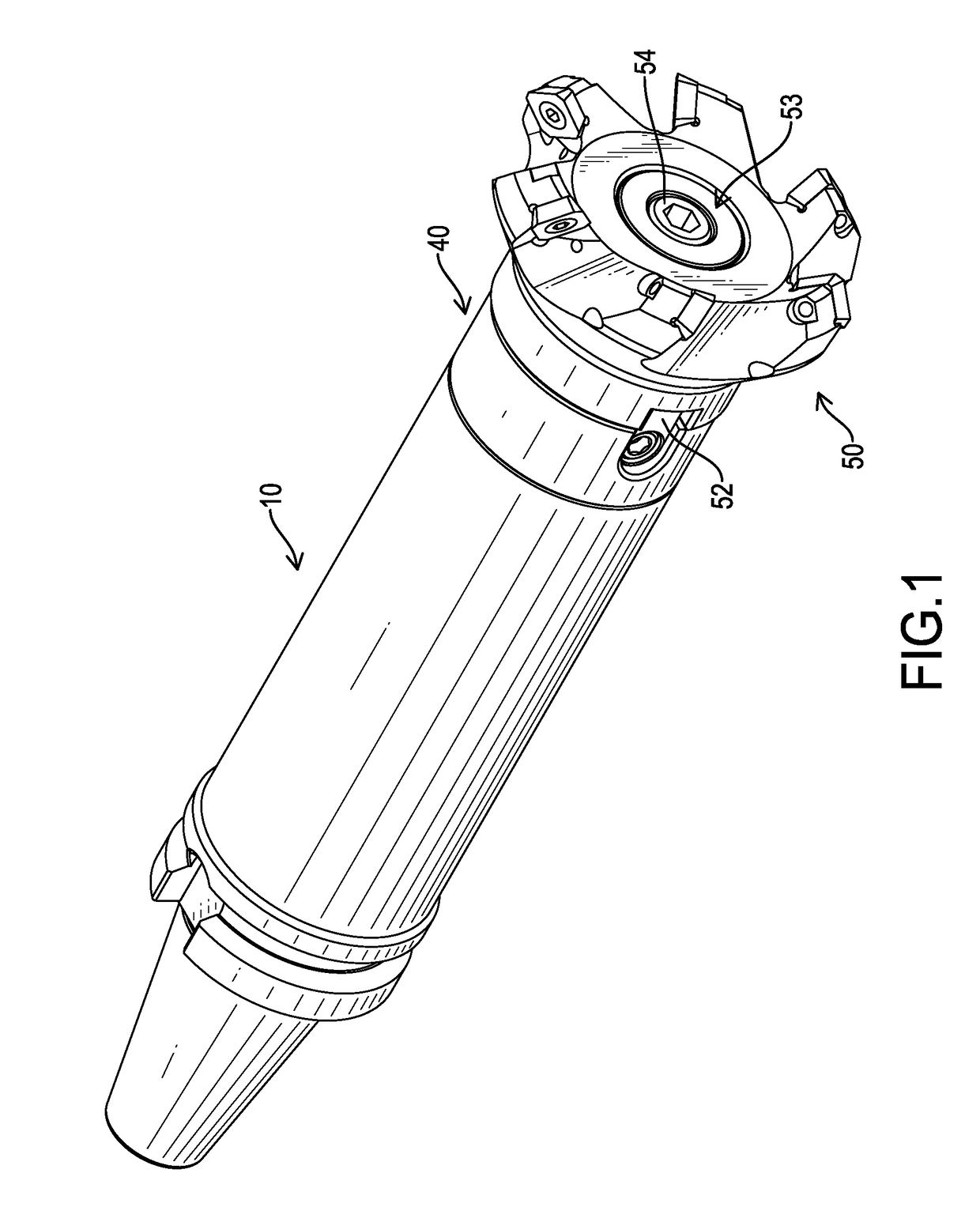
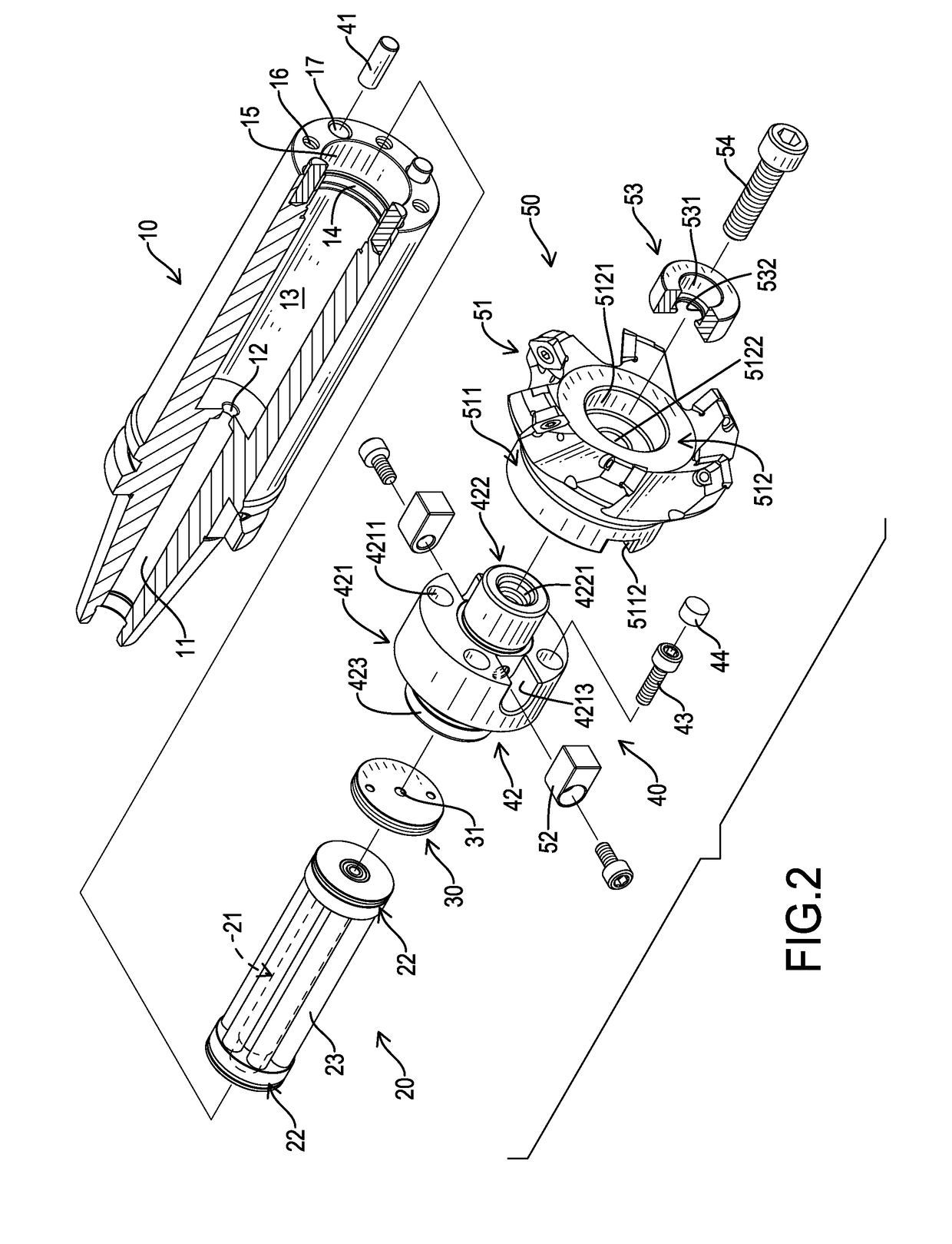
[0012]With reference to FIGS. 1, 2, and 4, a vibration resistant cutter holder in accordance with the present invention comprises a body 10, a damping assembly 20, a limiting unit 30, a fastening assembly 40, and a cutter assembly 50. The damping assembly 20 is contained inside the body 10. The limiting unit 30 is mounted in the body 10 and abuts against the damping assembly 20. The fastening assembly 40 is assembled on the body 10. The cutter assembly 50 is assembled on the fastening assembly 40.

[0013]With reference to FIGS. 2 and 4, the body 10 has a specific weight, a longitudinal direction, a first end, a second end, a guiding hole 11, a communicating hole 12, a receiving hole 13, a connecting hole 14, a mounting hole 15, four connecting threaded holes 16, and four pin holes 17. The longitudinal direction is along a central line C as shown in FIG. 4. The first end and the second end of the body 10 are opposite each other in the longitudinal direction of the body 10. The second e...


PUM


Abstract

A cutter holder has a body and a damping assembly. The damping assembly is contained inside the body. The damping assembly has a central damping pole and six auxiliary damping poles. The six auxiliary damping poles are arranged around the central damping pole. The body has a specific weight. The central damping pole has a specific weight larger than the specific weight of the body. Each one of the six auxiliary damping poles has a specific weight larger than the specific weight of the body. The damping assembly is utilized to reduce vibrations caused by machining.

Description

BACKGROUND OF THE INVENTION1. Field of the Invention[0001]The present invention relates to a machine tool, and more particularly to a cutter holder that can resist vibrations caused by machining.2. Description of Related Art[0002]Vibrations of a cutter holder easily occur as the rigidness of the cutter holder is insufficient, the frequency of the reaction force and the resonance frequency of the cutter holder are similar, or the cutter holder is suddenly encountered with an intense reaction force. Generally, the conventional cutter holder inevitably generates vibrations during machining. The vibrations have little influence on processing quality when utilizing cutter holders with shorter lengths. However, for cutter holders with longer lengths, the vibrations decrease the efficiency of machining, generate noise, and form obvious marks of machining and a rough surface on a work piece. The conventional cutter holder lacks vibration resistant structures and consequently brings about ne...

Claims


Application Information

Patent Timeline
Patent Type & Authority Applications(United States)
IPC IPC(8): B23C5/00B23B27/00B23C5/06
CPCB23C5/003B23C5/06B23B2250/16B23C2250/16B23B27/002B23B29/022B23B31/11B23Q11/0032
Inventor CHEN, CHING-TING
Owner CHEN CHING TING
Why Eureka
Try Eureka