Method Of Producing Membrane Electrode Assembly

Active Publication Date: 2018-01-11
HONDA MOTOR CO LTD
View PDF2 Cites 0 Cited by
  • Summary
  • Abstract
  • Description
  • Claims
  • Application Information

AI Technical Summary

Benefits of technology

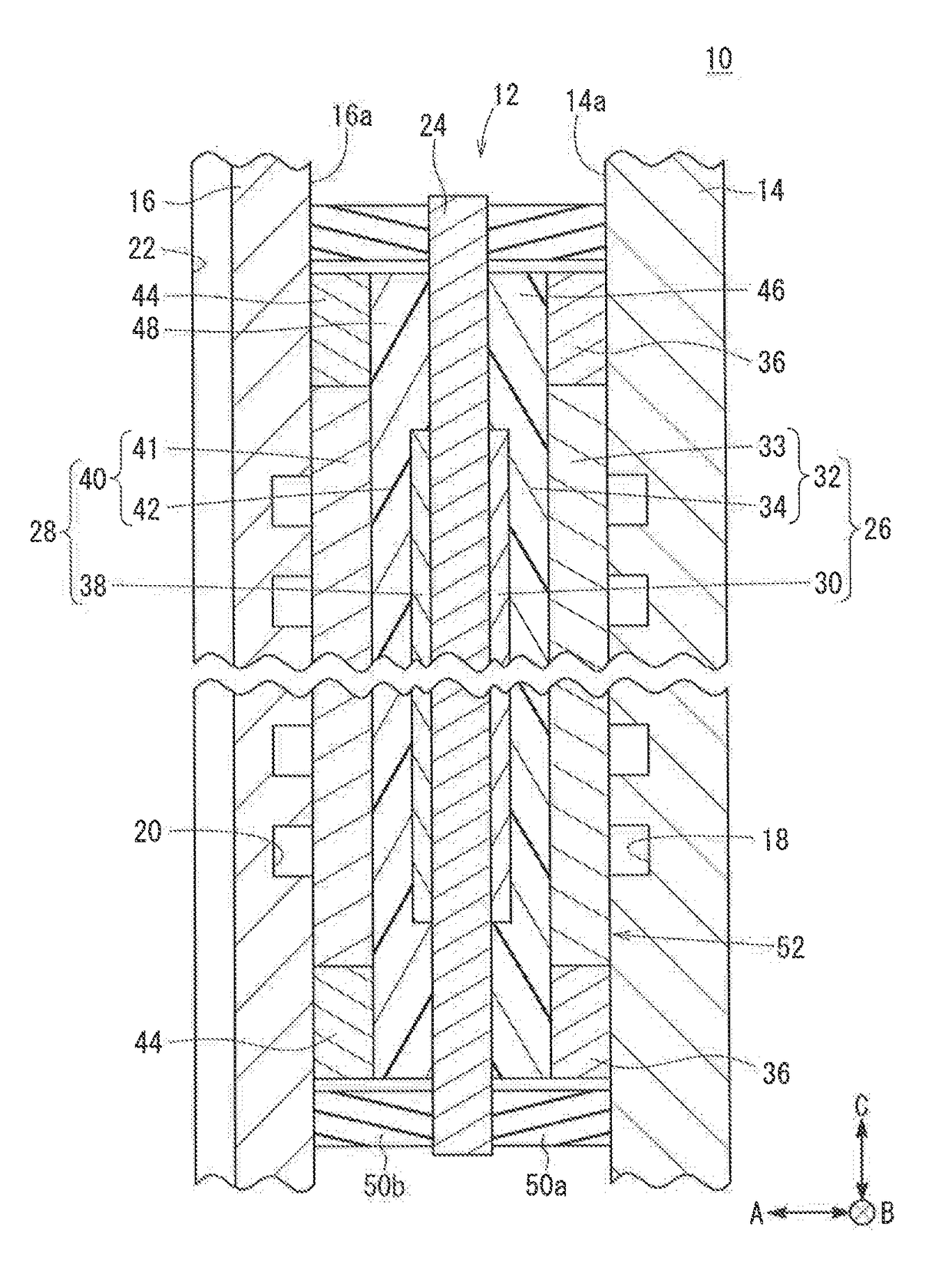
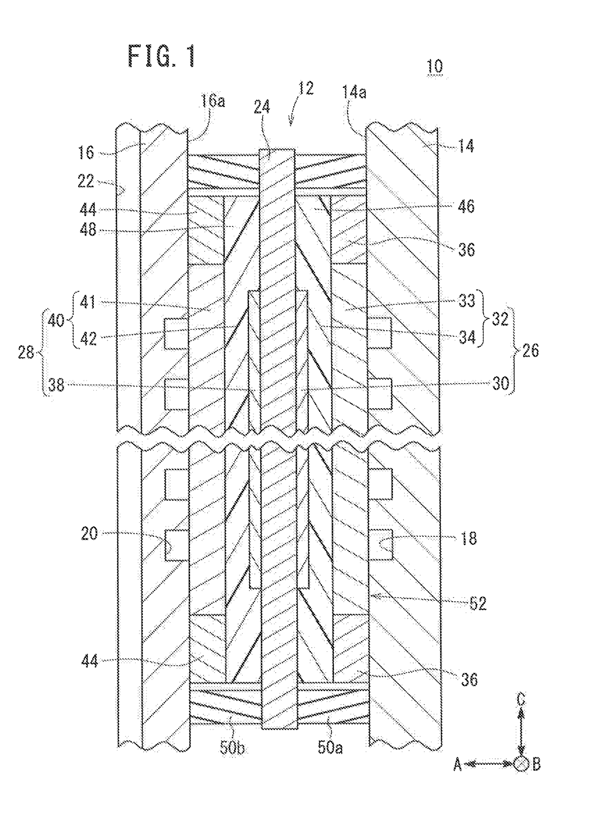
The present invention provides a method for producing a membrane electrode assembly by stacking gas diffusion layers, electrode catalyst layers, and a solid polymer electrolyte assembly together, and joining them integrally without requiring any heating from the outside. This results in an assembly with excellent power generation performance using simple facilities efficiently at low cost. Additionally, the method prevents excessive softening of the porous layers and ensures close contact between the layers, thereby improving the performance of the membrane electrode assembly.

Problems solved by technology

Therefore, because of the time period of heat transmission, extra time is required until completion of thermo-coupling, and it is difficult to improve the production efficiency of the membrane electrode assembly.
However, if the load is large, losses occur easily in the porous structure of the electrode, and damage occurs easily in the solid polymer electrode.
Therefore, there is a concern that the power generation performance of the resulting membrane electrode assembly is degraded undesirably.
Further, since it is necessary to increase and maintain the temperature of the mold up to a hot temperature which enables thermo-coupling, there is a concern that significant running cost is required, and moreover, production facilities are complicated.

Method used


Image

  • Method Of Producing Membrane Electrode Assembly
  • Method Of Producing Membrane Electrode Assembly
  • Method Of Producing Membrane Electrode Assembly

Examples


embodiment example 1

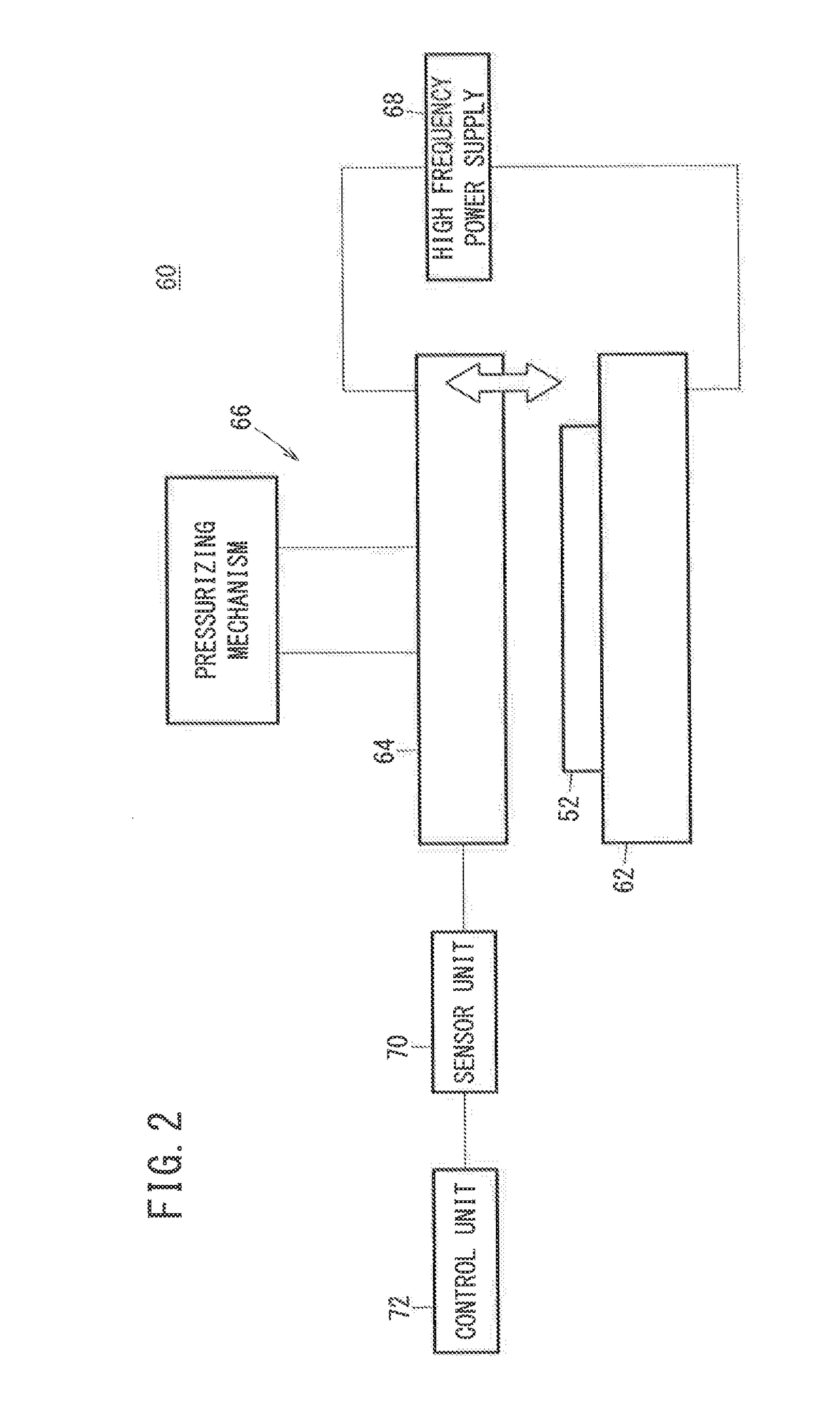
[0082]A load was applied to the stack body in the stacking direction, and the temperature of the solid polymer electrolyte membrane was increased by high frequency dielectric heating to join the gas diffusion layers, the electrode catalyst layers, and the solid polymer electrolyte membrane were joined integrally. At this time, high frequency dielectric heating was performed under a certain condition. Using different magnitudes of loads, three membrane electrode assemblies according to the embodiment example 1 were obtained. Specifically, high frequency dielectric heating was performed under the condition where the processing time was 5 seconds, the frequency of the high frequency electric field was 40 MHz, and the temperature of the solid polymer electrolyte membrane was increased to 150° C. Further, the loads applied to the stack body were 2 kgf / cm2 (19.6 N / cm2), 10 kgf / cm2 (98 N / cm2), and 15 kgf / cm2 (147 N / cm2), respectively.

embodiment example 2

[0083]A load of 15 kgf / cm2 (147 N / cm2) was applied to the stack body in the stacking direction, and the temperature of the solid polymer electrolyte membrane was increased to 100° C. by high frequency dielectric heating to join the gas diffusion layers, the electrode catalyst layers, and the solid polymer electrolyte membrane integrally to obtain the membrane electrode assembly according to the embodiment example 2. High frequency dielectric heating was performed under the condition where the processing time was 5 seconds, and the frequency of the high frequency electric field was 40 MHz.

embodiment example 3

[0084]A membrane electrode assembly according to a third embodiment example 3 was obtained in the same manner as the embodiment example 2 except that the load of 2 kgf / cm2 (19.6 N / cm2) was applied to the stack body in the stacking direction.


PUM


Abstract

In a method of producing a membrane electrode assembly, a solid polymer electrolyte membrane and gas diffusion layers are stacked together in a stacking direction in a manner that electrode catalyst layers are interposed between at least parts of the solid polymer electrolyte membrane and the gas diffusion layers to form a stack body. A load is applied to the stack body in the stacking direction, and the temperature of the solid polymer electrolyte membrane is increased by high frequency dielectric heating. In this manner, the gas diffusion layers, the electrode catalyst layers, and the solid polymer electrolyte membrane are joined integrally to obtain the membrane electrode assembly.

Description

CROSS-REFERENCE TO RELATED APPLICATION[0001]This application is based upon and claims the benefit of priority from Japanese Patent Application No. 2016-133016 filed on Jul. 5, 2016, the contents of which are incorporated herein by reference.BACKGROUND OF THE INVENTIONField of the Invention[0002]The present invention relates to a method of producing a membrane electrode assembly. The membrane electrode assembly includes a solid polymer electrolyte membrane and electrodes provided on both sides of the solid polymer electrolyte membrane, respectively. Each of the electrodes includes a gas diffusion layer and an electrode catalyst layer.Description of the Related Art[0003]A unit cell of a solid polymer fuel cell is formed by sandwiching a membrane electrode assembly between a pair of separators. The membrane electrode assembly includes a pair of electrodes (an anode and a cathode) and a solid polymer electrolyte membrane interposed between the electrodes. The solid polymer electrolyte m...

Claims


Application Information

Patent Timeline
IPC IPC(8): H01M8/14H01M4/88H05B6/54
CPCH01M8/141H01M4/8807H01M4/88H01M8/1004H05B6/54H01M8/0241H05B6/50H05B6/62Y02P70/50Y02E60/50
Inventor KITAGAWA, TAICHIKONNO, YOSUKE
Owner HONDA MOTOR CO LTD
Why Eureka
Try Eureka