
Control device and method for jointly controlling asynchronous machines of a motor vehicle

a technology of asynchronous machines and control devices, which is applied in the direction of electric devices, transportation and packaging, propulsion by batteries/cells, etc., can solve the problems of natural limitations, and achieve the effect of significantly reducing installation space and weigh

Active Publication Date: 2018-01-11
ROBERT BOSCH GMBH
View PDF1 Cites 1 Cited by
  • Summary
  • Abstract
  • Description
  • Claims
  • Application Information

AI Technical Summary

Benefits of technology

The patent text describes a method for controlling multiple asynchronous machines in a motor vehicle using only one inverter. This reduces installation space and weight compared to conventional solutions. The method can be applied to any type of motor vehicle with at least two asynchronous machines, and may also be expanded to applications with more than two machines. The method takes into account information from an ESP system to determine the allowed torque for each machine and to establish an operating strategy for them based on the current driving situation. The method can also adjust the distribution of torque to compensate for potential deviations from the setpoint state. The refinement reduces the impact of common driving situations on the performance of the vehicle.

Problems solved by technology

Due to the fact that motor vehicles comprise a continuously increasing number of mechanical, hydraulic, and electrical components, it makes sense, however, to utilize the space inside the motor vehicle, which is naturally limited, in an optimal way.

Method used


Image

  • Control device and method for jointly controlling asynchronous machines of a motor vehicle
  • Control device and method for jointly controlling asynchronous machines of a motor vehicle
  • Control device and method for jointly controlling asynchronous machines of a motor vehicle

Examples


Embodiment Construction

[0025]In the figures, identical reference numbers designate elements that are identical or are functionally identical.

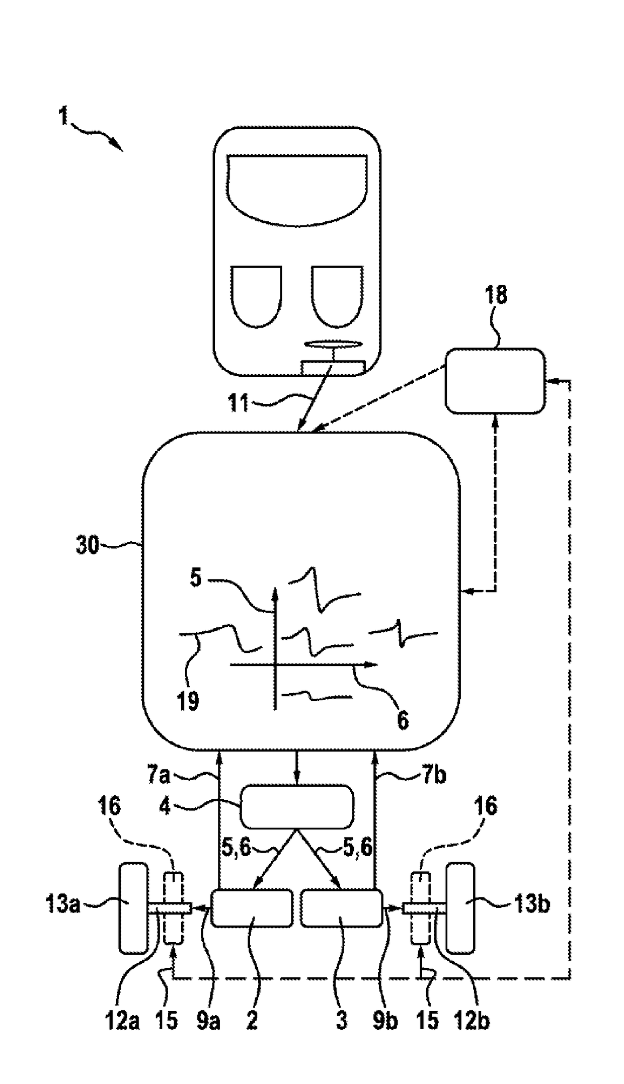
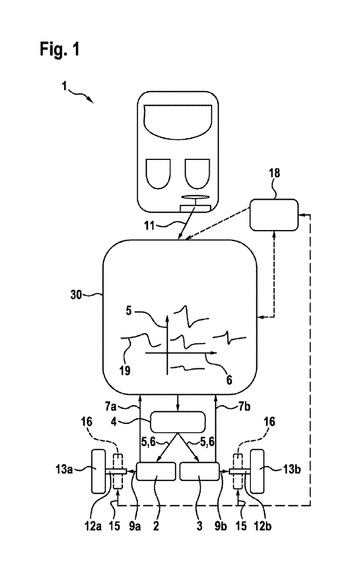
[0026]FIG. 1 shows a schematic depiction of a motor vehicle comprising two asynchronous machines and a control device for controlling a method for jointly controlling the asynchronous machines according to one embodiment of the invention.

[0027]In FIG. 1, reference number 1 designates the motor vehicle. The motor vehicle 1 is designed having a first asynchronous machine 2 and a second asynchronous machine 3 on a first axle 12a, e.g., a front axle. The motor vehicle 1 can be, for example, a passenger car or the like, which is designed having a rear axle (not shown) having two wheels, and a front axle 12a having a first wheel 13a (right front wheel) and a second wheel 13b (left front wheel). The present invention is described in the following on the basis of this exemplary embodiment of a passenger car comprising two asynchronous machines 2; 3 on the front axle 12a.

[00...


PUM


Abstract

The invention relates to a method for jointly controlling asynchronous machines (2; 3) of a motor vehicle (1) having a first asynchronous machine (2) and a second asynchronous machine (3) for driving the motor vehicle (1); an inverter (4), which is designed to supply the first asynchronous machine (2) and the second asynchronous machine (3) with a common stator voltage (5) at a common stator frequency (6). The method comprises the steps of determining a specified setpoint drive torque (11) of the motor vehicle (1) for a current driving situation of the motor vehicle (1); sensing a first rotational speed (7a) of the first asynchronous machine (2) and a second rotational speed (7b) of the second asynchronous machine (3); determining a common operating strategy of the first asynchronous machine (2) and of the second asynchronous machine (3) according to the specified setpoint torque (11) while taking into account the sensed rotational speeds (7a; 7b); and controlling the stator voltage (5) and the stator frequency (6) in order to set the drive torques (9a; 9b) of the asynchronous machines (2; 3) according to the operating strategy.

Description

BACKGROUND OF THE INVENTION[0001]The invention relates to a method for jointly controlling asynchronous machines of a motor vehicle, and to a control device for controlling such a method.[0002]Although the present invention and the underlying problem thereof are described with reference to an electric vehicle comprising two asynchronous machines (ASM), each of which drives one wheel of a shared vehicle axle, the invention can also be applied to any other motor vehicles comprising multiple asynchronous machines in different configurations at the wheels and / or the vehicle axles of the particular motor vehicle.[0003]In many applications of electric drive technology, situations occur in which it is advantageous to install two or more electrical machines in a motor vehicle. In the field of electric or hybrid-electric vehicles, a multiplicity of different topologies for the configuration of the drive train are utilized, in which multiple asynchronous machines or the like can be arranged i...

Claims


Application Information

Patent Timeline
IPC IPC(8): H02P5/74B60L7/14B60W10/08B60L15/20B60L3/10B60W10/06B60L11/18
CPCH02P5/74B60L11/18B60L7/14B60L3/106B60L15/2036B60W20/40B60W10/06B60W10/08H02P2207/01B60L2220/12B60L2220/42B60W2550/148B60W2550/12Y10S903/93B60L50/60Y02T10/64Y02T10/72Y02T10/70B60W2552/40B60W2555/20B60L3/10
Inventor GROSSMANN, EKARD
Owner ROBERT BOSCH GMBH
Learn More