Method and system for measuring the angular velocity of a body orbiting in space

Inactive Publication Date: 2018-01-18
POLITECNICO DI TORINO
View PDF3 Cites 3 Cited by
  • Summary
  • Abstract
  • Description
  • Claims
  • Application Information

AI Technical Summary

Benefits of technology

[0047]Further advantageous characteristics will be more clear from the following description of p

Problems solved by technology

On average, every day an object catalogued to be more than 10 cm in diameter falls on Earth, and therefore the fundamental problem is identifying said objects in orbit also in connection with the prevention of risks related to the so called NEOs (Near Earth Objects).
The re-entry risk is not only due to the mechanical impact, but also to chemical or radiological environmental contamination; moreover space debris can compromise the operation of active satellites damaging them by collision or reducing their performances by being deposited on surfaces of optical systems, degrading solar panels and antennas, thus reducing their transmitting ability and causing interferences with signals.
However the above invention does not provide to measure the angular velocity of a body orbiting in space.
The disadvantages of the methods and systems described above substantially are the fact that for being used they need operating sensors to be on board the satellite.
The solution according to such document allows the attitude and the angular velocity of the satellite to be determined over time; however such solution cannot be applied independently of the use of said star video cameras placed on board the spacecraft.
However the solutions described in the above applications to Needelman et al. are not able to estimate attitude and angular velocity of the satellite if the on-board instruments are subjected to any malfunctions.
Finally the Chinese patent application n. CN101706512 to Chen et al., (see reference [9]) describes a method, and related system, for estimating the angular velocity of satellites by a Kalman filter by using the combination of satellite orientation measurements and measurements of angular momentum; however such solution requires further measurements in addition to the orientation one and therefore it is less effective than the solutions mentioned above.
The method has been used in the present invention, besides treating the attitude measurements, also for de-noising the angular velocity estimated by Kalman filter, thus avoiding the use of LTI (Linear Time-Invariant) filters that are usually used for removing high frequency noise from a given signal, but that, with the measurement of the angular velocity of a body orbiting in space are not effective.
Therefore there is the unsatisfied need of carrying out the estimate of the attitude and angular velocity conditions of a “dead” body orbiting in space, for example a satellite with no instrument on board for measuring said attitude or said angular velocity or whose sensors are damaged and unusable.
Moreover there is the unsatisfied need of carrying out the estimate of said attitude and angular velocity conditions indirectly by means of remote instruments able to acquire the position of few feature points of the outer surface of the “dead” body in orbit.
Such measurements can be possibly affected by errors and not be acquired with a constant rate.

Method used


Image

  • Method and system for measuring the angular velocity of a body orbiting in space
  • Method and system for measuring the angular velocity of a body orbiting in space
  • Method and system for measuring the angular velocity of a body orbiting in space

Examples


example

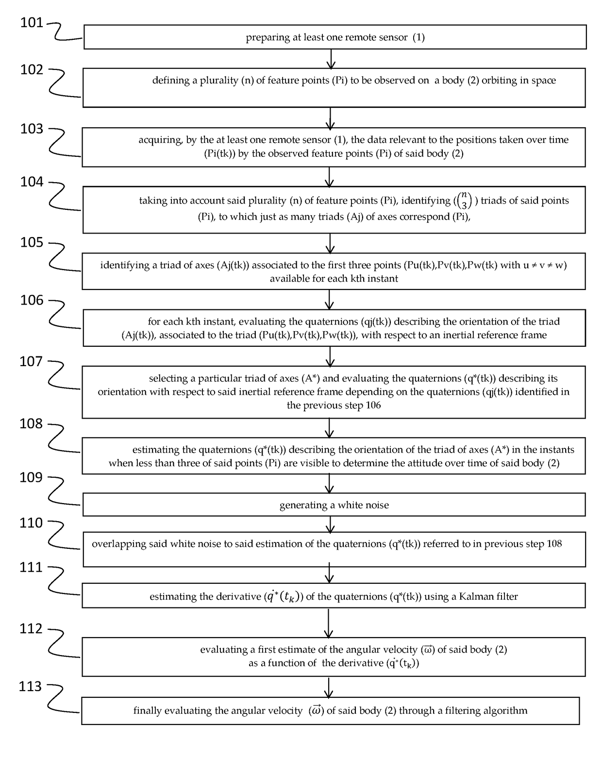
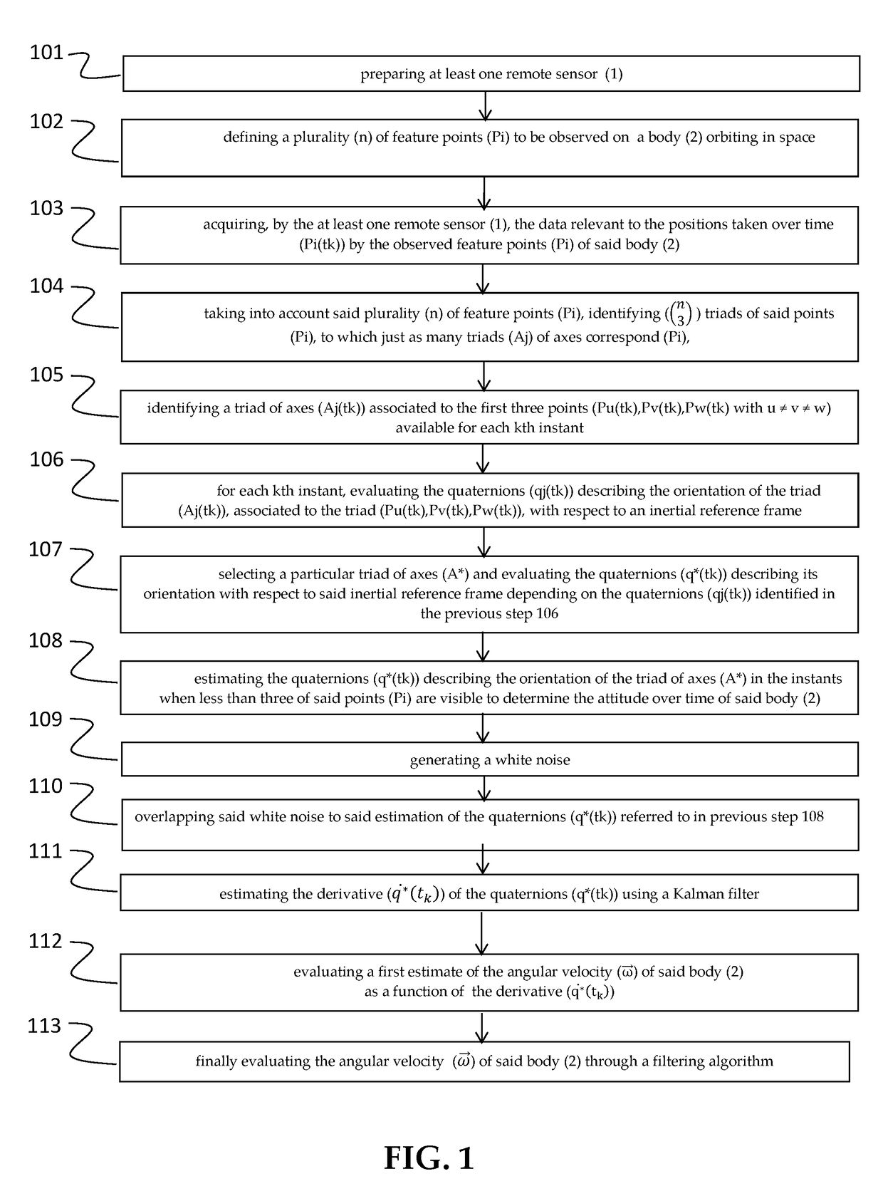
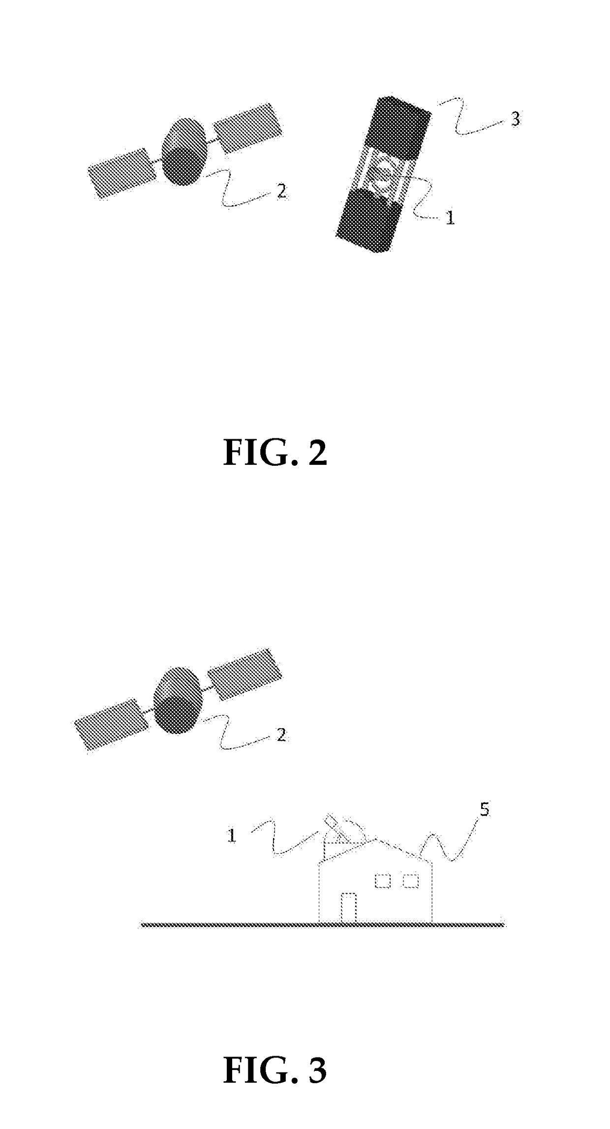
[0117]Measurement of the angular velocity of a body 2 orbiting in space by means of a remote sensor 1 installed on board a spacecraft 3.

[0118]The body 2 orbiting in space has five feature points whose Euclidean coordinates are listed with reference to a principal central inertial reference frame:

P1[4.00 0.00 0.00]mP2[−5.71 0.00 −0.81]mP3[−3.91 0.00 1.42]mP4[−3.97 1.02 −1.02]mP5[−7.61 0.00 0.00]m

[0119]The orbit of said body 2 orbiting in space is defined by the following ephemerides:

e 0.55i 6.93°ω146.40°Ω132.20°h544.00 kmθ0349.90°

[0120]Where e is eccentricity, i orbit inclination, ω the argument of perigee, Ω is the longitude of the ascending node, h is height at perigee and θ0 is the true anomaly at instant t0.

[0121]The initial velocity of the body expressed with respect to the b frame is:

b{right arrow over (ω)}0=[0.17 0.01 −0.29]rad / s

[0122]The principal moments of inertia of said body 2 are:

bI=[22435 18430 13420]kg m2

[0123]The body 3, on which the sensor 1 is placed, is controlled...


PUM


Abstract

The invention relates to a method for measuring the angular velocity ({right arrow over (ω)}) of a body (2) orbiting, or in motion anyway, in space depending on the detection of the trajectory of a plurality (n) of feature points (Pi) to be observed of said body (2), said trajectory being detected on the basis of data acquired by at least one remote sensor (1); the invention relate also to the related system for measuring the angular velocity ({right arrow over (ω)}) of a body (2) orbiting, or in motion anyway, in space using such method and that comprises at least one remote sensor (1), it being possible for said at least one sensor (1) to be installed on board a spacecraft (3) or to be housed in a earth station (5).The present invention has a preferred application for measuring the angular velocity in fields such as for recovering and de-orbiting space debris.

Description

TECHNICAL FIELD[0001]The present invention relates to space sector, and specifically, to the identification of objects in orbit in space such to capture them and then to disintegrate or transfer them to another orbit.[0002]More specifically, the present invention relates to a method, and related system, for measuring the angular velocity of one or more objects orbiting in space.[0003]The invention has a preferred and advantageous application when employed for recovering and de-orbiting space debris and also for intercepting and then destroying or migrating asteroids, potentially colliding with Earth, into a controlled orbit.PRIOR ART[0004]There are two types of space debris (also known as orbital debris, space junk or space waste): natural and artificial types; natural space debris are composed of small fragments of material from comets and asteroids while artificial space debris are all the non-functional artificial objects present in space, usually in orbit around Earth. The first...

Claims


Application Information

Patent Timeline
IPC IPC(8): B64G3/00G01P3/38
CPCB64G3/00G01P3/38B64G1/66G01C19/00
Inventor MAURO, STEFANOPASTORELLI, STEFANOMOHTAR EIZAGA, THAREK MANUELBIONDI, GABRIELESORLI, MASSIMO
Owner POLITECNICO DI TORINO
Why Eureka
Try Eureka