Filter screens and methods of making filter screens

Active Publication Date: 2018-01-18
COLLINS ENGINE NOZZLES INC
View PDF5 Cites 3 Cited by
  • Summary
  • Abstract
  • Description
  • Claims
  • Application Information

AI Technical Summary

Benefits of technology

[0005]A filter screen includes a plate body with an upstream surface, an opposed downstream surface, and an array of apertures extending between the upstream surface and the downstream surface. A polytetrafluoroethylene (PTFE)-based layer overlays the upstream surface bet

Problems solved by technology

Such carbonaceous depositions can accumulate over time, potentially binding together movable structures, occluding fuel system components, and/or affecting fuel flow through the fuel system.
Coking ca

Method used


Image

  • Filter screens and methods of making filter screens
  • Filter screens and methods of making filter screens
  • Filter screens and methods of making filter screens

Examples


Embodiment Construction

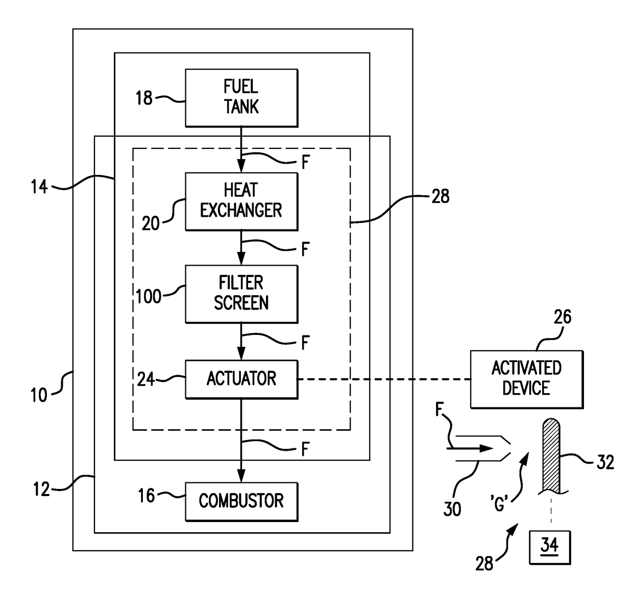
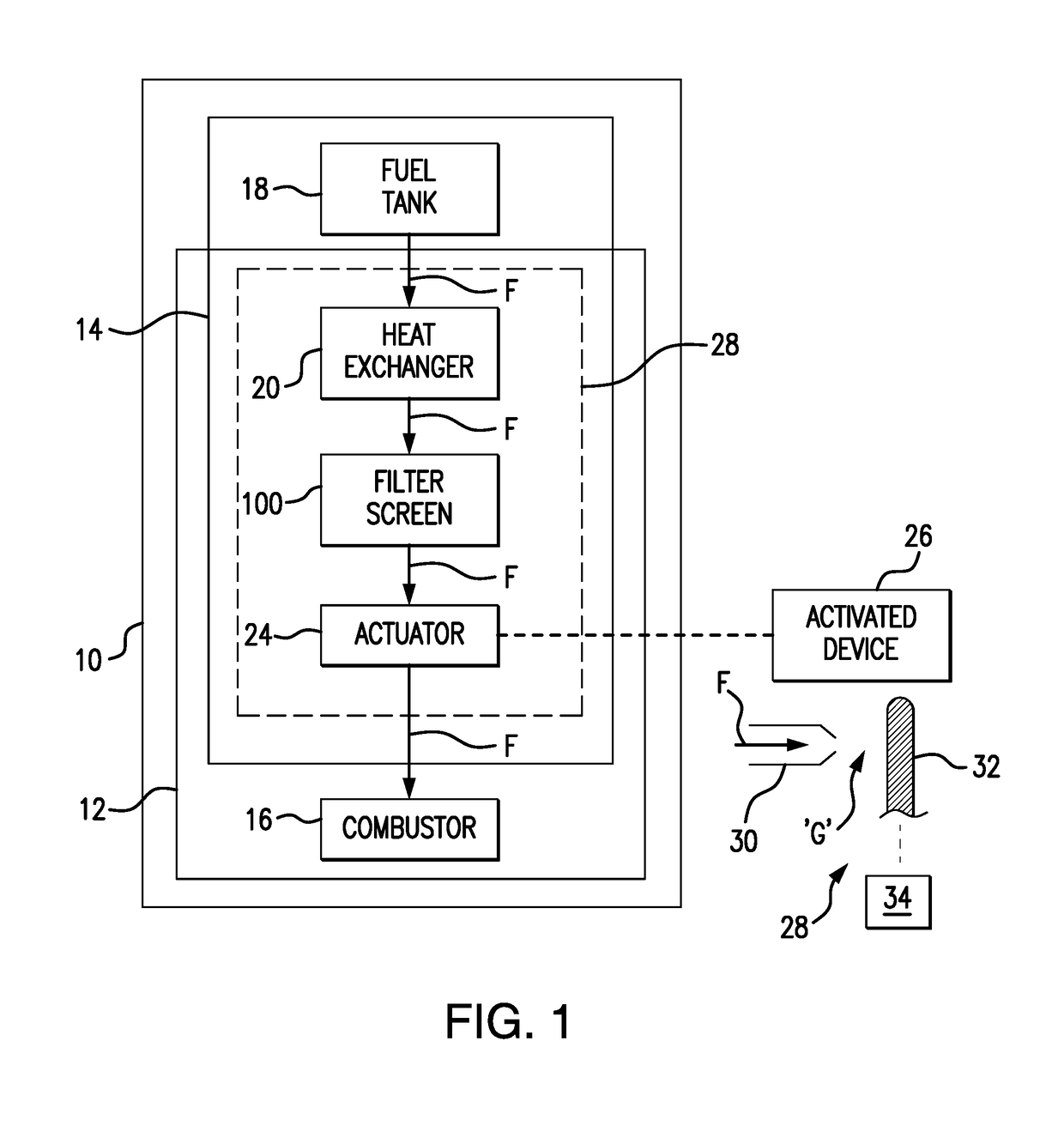
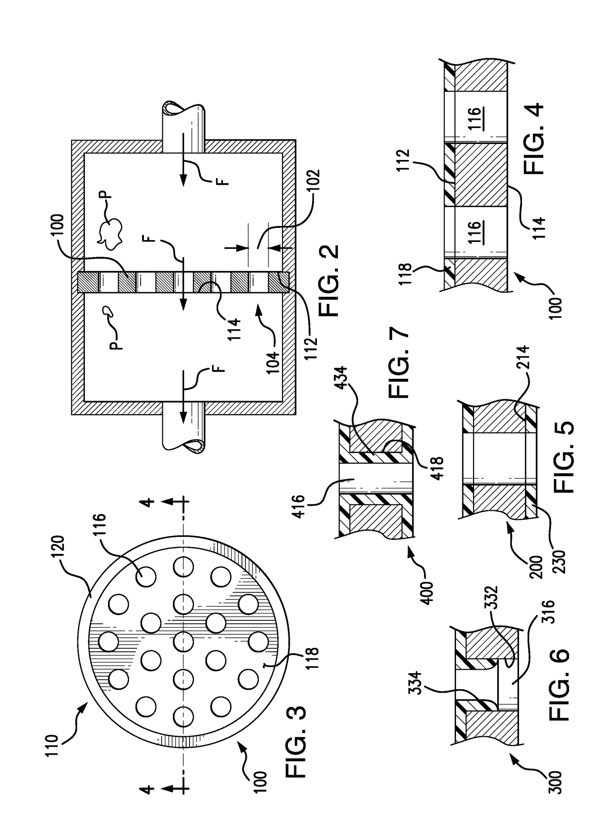
[0018]Reference will now be made to the drawings wherein like reference numerals identify similar structural features or aspects of the subject disclosure. For purposes of explanation and illustration, and not limitation, a partial view of an exemplary embodiment of a filter screen in accordance with the disclosure is shown in FIG. 1 and is designated generally by reference character 100. Other embodiments of filter screens, servo nozzle actuators in gas turbine engine fuel systems employing such filter screens, and methods of making such filter screens in accordance with the disclosure, or aspects thereof, are provided in FIGS. 2-8, as will be described. The systems and methods described herein can be used for ‘last chance’ filter screens in fuel and / or lubrication systems, though the present disclosure is not limited to fuel systems, lubrication systems, or any other particular type of filter screen application.

[0019]Referring to FIG. 1, an aircraft 10 is shown. Aircraft 10 includ...


PUM

PropertyMeasurementUnit
Thicknessaaaaaaaaaa
Thicknessaaaaaaaaaa
Widthaaaaaaaaaa

Abstract

A filter screen includes a plate body with an upstream surface, an opposed downstream surface, and an array of apertures extending between the upstream surface and the downstream surface. A polytetrafluoroethylene-based layer overlays the upstream surface between apertures of the aperture array, the polytetrafluorethylene-based layer being conformally disposed over the upstream surface of the plate body and spanning the upstream surface between the apertures of the aperture array to slow deposition of carbonaceous deposits on the filter screen.

Description

BACKGROUND OF THE INVENTION1. Field of the Invention[0001]The present disclosure relates to fluid flow, and more particularly to fluid flow through fuel systems in gas turbine engines.2. Description of Related Art[0002]Gas turbine engines, such as aircraft main engines and auxiliary power units, commonly have fuel systems that convey hydrocarbon-based fuels to the combustor section of the gas turbine engine. In some gas turbine engines, the fuel system is also used to provide cooling for hot engine components and / or to provide actuation force for fluid-powered devices. Fuel in such systems may be recirculated or used for cooling prior to reaching the combustion section.[0003]While heating fuel can be advantageous, such as by preventing ice formation within a fuel flow, heating fuel above a certain temperature threshold can increase the tendency of ‘coking’ within the fuel system. Coking typically involves the deposition of carbonaceous materials on fuel system internal structures, e...

Claims


Application Information

Patent Timeline
IPC IPC(8): F02C7/224B01D35/00B01D39/20F02C7/14B01D29/00B01D29/01C09D127/18
CPCF02C7/224B01D35/005B01D29/0095B01D39/2027F05D2220/32F02C7/14C09D127/18B01D2239/0478B01D2239/1216B01D29/012F02C7/222F05D2300/432F16L58/1009
Inventor CORDATOS, HARALAMBOSPROCIW, LEV ALEXANDERREUTER, CHARLES E.CANNATA, JOHN D.MARTUCCI, ANGELOBELONCIK, SCOTT J.
Owner COLLINS ENGINE NOZZLES INC
Why Eureka
Try Eureka