Optical line testing device using wavelength tunable laser

a testing device and wavelength technology, applied in the direction of optical apparatus testing, structural/machine measurement, instruments, etc., can solve the problems affecting the accuracy of optical lines, so as to achieve the effect of reducing the dynamic range, reducing the resolution of optical lines, and increasing the optical power of optical signals for measuremen

Active Publication Date: 2018-01-18
SOLID
View PDF5 Cites 9 Cited by
  • Summary
  • Abstract
  • Description
  • Claims
  • Application Information

AI Technical Summary

Benefits of technology

[0026]a variable delay time is given to a second optical signal generated from the other one of the two wavelength tunable laser sources, and the optical line testing device is configured to measure the cutting position using an interference effect when the round trip time, corresponding to the first optical signal, which is returning after having been emitted to the optical line, is equal to or an integral multiple of the delay time of the second optical signal, and is configured to measure an output of an interference signal while varying the delay time.
[0027]According to an embodiment of the present invention, unlike an optical pulse, optical power of a used optical signal is constant or continuous, so that even if the optical power increases, a nonlinear effect bet

Problems solved by technology

First, it is difficult to increase a dynamic range. The dynamic range refers to a distance the OTDR can measure. To increase the range, it is necessary to increase magnitude of the optical pulse. However, if the magnitude of the optical pulse is increased beyond a threshold value, a nonlinear effect due to an interaction between the optical line and the optical pulse is strongly generated

Method used


Image

  • Optical line testing device using wavelength tunable laser
  • Optical line testing device using wavelength tunable laser
  • Optical line testing device using wavelength tunable laser

Examples


Embodiment Construction

[0039]Features and advantages of the present invention will become apparent from the following detailed description of the present invention with reference to the accompanying drawings, and it will be understood by those of ordinary skill in the art that various changes in form and details may be made therein without departing from the spirit and scope of the present invention. Furthermore, in the description of the present invention, certain detailed explanations of the related art are omitted when it is deemed that they may unnecessarily obscure the essence of the present invention. Reference will now be made in detail to embodiments of the present invention, examples of which are illustrated in the accompanying drawings.

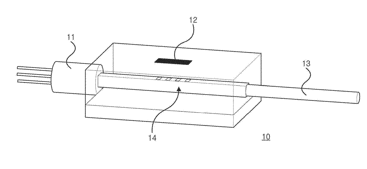
[0040]FIG. 4 is a block diagram of an optical line testing device 100 according to an embodiment of the present invention.

[0041]The optical line testing device 100 according to an embodiment of the present invention is for measuring at least a cutting position of ...


PUM


Abstract

An optical line testing device for measuring at least a cutting position of an optical line according to the present invention includes: a first wavelength tunable laser source configured to generate a first optical signal in which a plurality of wavelengths appear alternately and periodically; a second wavelength tunable laser source configured to generate a second optical signal which is identical to the first optical signal but has an adjustable delay time; and an interferometer configured to cause interference between a reflected optical signal, corresponding to the first optical signal, which is returning after having been emitted to the optical line, and the second optical signal to output an interference signal.

Description

CROSS-REFERENCE TO RELATED APPLICATIONS[0001]This application is a National Stage of International Application No. PCT / KR2015 / 014061, filed Dec. 22, 2015, and claims priority from Korean Patent Applications No. 10-2014-0188002 filed Dec. 24, 2014, the contents of which are incorporated herein by reference in their entireties.BACKGROUND1. Field[0002]The present invention relates to an optical line testing device such as an Optical Time Domain Reflectometer (OTDR), and more particularly, to an optical line testing device using a wavelength tunable laser.2. Description of the Related Art[0003]As communication volume increases, copper-based communication cables are replaced by optical fiber-based optical lines. The optical lines have been installed only in a section connecting a telephone office and a telephone office, but due to the increase in multimedia services such as Video On Demand (VOD), the optical lines are now being installed in homes or each room of the homes like a Fiber To...

Claims


Application Information

Patent Timeline
IPC IPC(8): G01M11/00H04B10/50H04B10/079H04B10/572
CPCG01M11/3127G01M11/3181H04B10/0799H04B10/0795H04B10/503H04B10/572G01M11/00G01M11/02H04B10/071G01M11/3145G01M11/331
Inventor NA, KEEWOON
Owner SOLID
Why Eureka
Try Eureka