Optical Image Capturing System

a technology of optical system and image, applied in the field of compact, can solve the problems of occupying a significant amount of space for the elements of the icr, affecting the design and manufacture of miniaturized surveillance cameras in the future, and high cost, so as to reduce the height of the optical system, reduce the incident angle of the off-axis ray, and improve the effect of image quality

Active Publication Date: 2018-01-18
ABILITY OPTO ELECTRONICS TECH
View PDF4 Cites 7 Cited by
  • Summary
  • Abstract
  • Description
  • Claims
  • Application Information

AI Technical Summary

Benefits of technology

[0006]The aspect of embodiment of the present disclosure directs to an optical image capturing system and an optical image capturing lens which use combination of refractive powers, convex and concave surfaces of four-piece optical lenses (the convex or concave surface in the present disclosure denotes the geometrical shape of an image-side surface or an object-side surface of each lens on an optical axis) to increase the amount of light admitted into the optical image capturing system and the angle of view of the optical lenses, and to improve total pixel count and the image quality, while possessing certain amount of relative illumination, so as to be applied to minimized electronic products.
[0007]In addition, when it comes to certain application of optical imaging, there will be a need to capture image via light sources with wavelengths in both visible and infrared ranges, an example of this kind of application is IP video surveillance camera, which is equipped with the Day & Night function. The visible spectrum for human vision has wavelengths ranging from 400 to 700 nm, but the image formed on the camera sensor includes infrared light, which is invisible to human eyes. Therefore, under certain circumstances, an IR cut filter removable (ICR) is placed before the sensor of the IP video surveillance camera, in order to ensure that only the light that is visible to human eyes is picked up by the sensor eventually, so as to enhance the “fidelity” of the image. The ICR of the IP video surveillance camera can completely filter out the infrared light under daytime mode to avoid color cast; whereas under night mode, it allows infrared light to pass through the lens to enhance the image brightness. Nevertheless, the elements of the ICR occupy a significant amount of space and are expensive, which impede to the design and manufacture of miniaturized surveillance cameras in the future.
[0008]The aspect of embodiment of the present disclosure directs to an optical image capturing system and an optical image capturing lens which utilize the combination of refractive powers, convex surfaces and concave surfaces of four lens elements, as well as the selection of materials thereof, to reduce the difference between the imaging focal length of visible light and imaging focal length of infrared light, in order to achieve the near “confocal” effect without the use of ICR elements.

Problems solved by technology

Nevertheless, the elements of the ICR occupy a significant amount of space and are expensive, which impede to the design and manufacture of miniaturized surveillance cameras in the future.

Method used


Image

  • Optical Image Capturing System
  • Optical Image Capturing System
  • Optical Image Capturing System

Examples


first embodiment

The First Embodiment

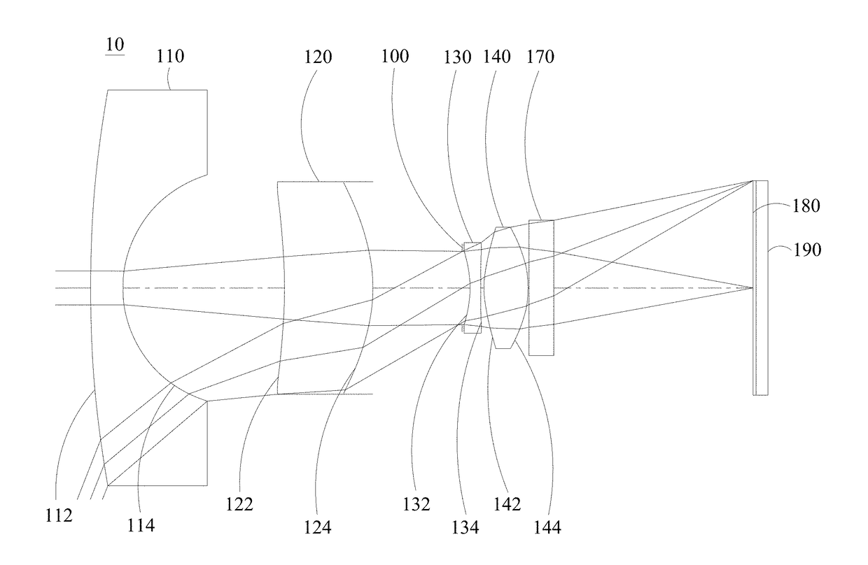
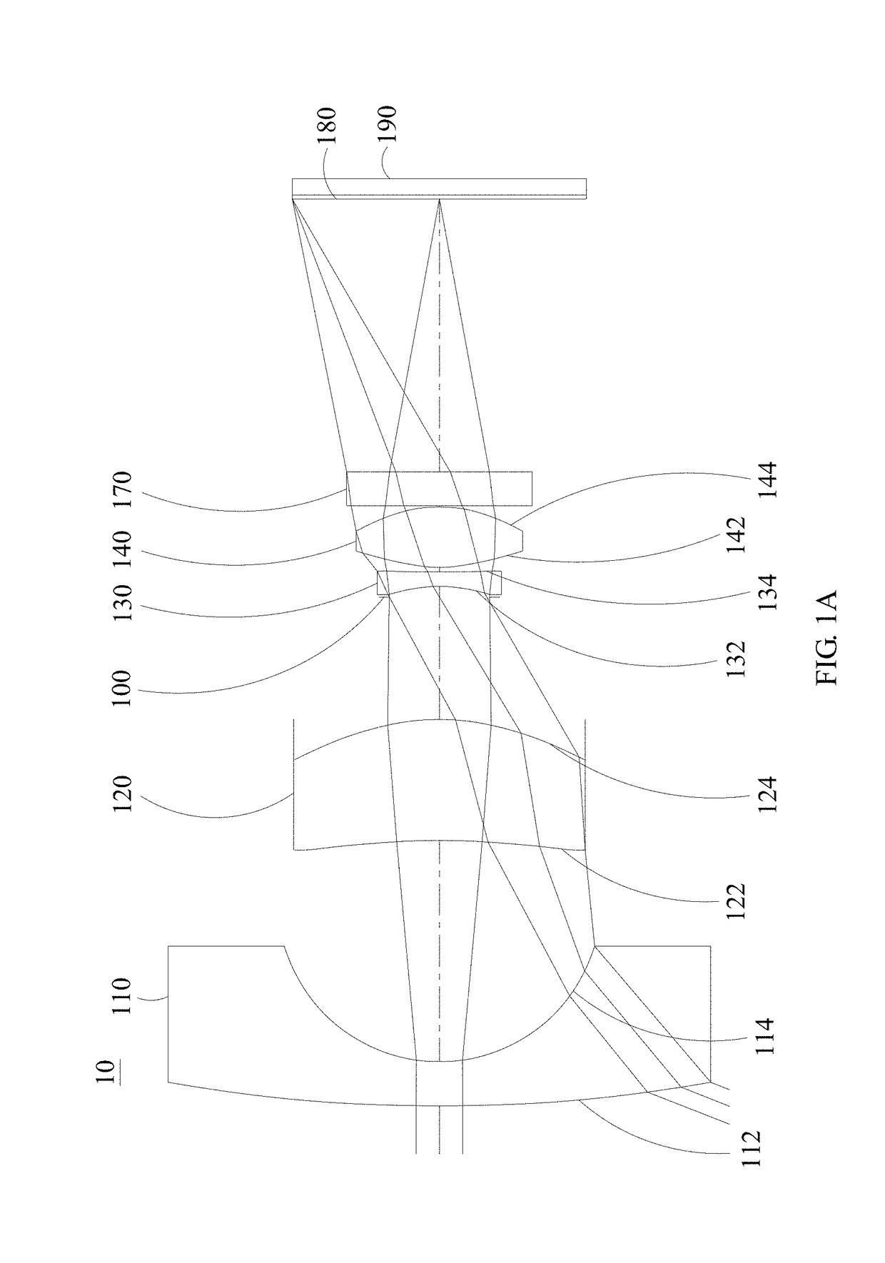
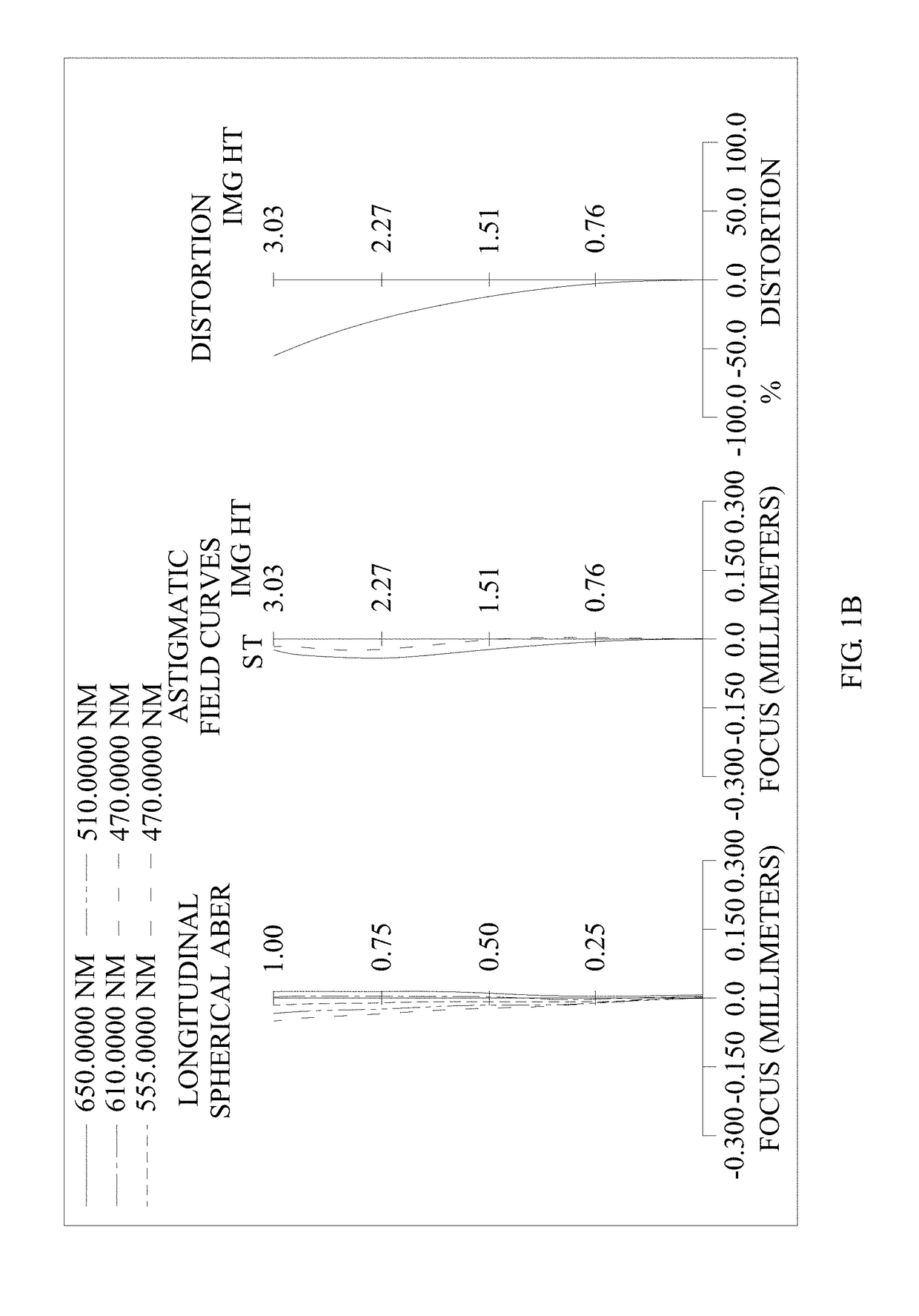
[0118]Please refer to FIGS. 1A to 1E. FIG. 1A is a schematic view of the optical image capturing system according to the first embodiment of the present disclosure. FIG. 1B shows the longitudinal spherical aberration curves, astigmatic field curves, and optical distortion curve of the optical image capturing system in the order from left to right according to the first embodiment of the present disclosure. FIG. 1C is a transverse aberration diagram of the longest operation wavelength and the shortest operation wavelength for tangential fan and sagittal fan, and the longest operation wavelength and the shortest operation wavelength pass through an edge of the entrance pupil and incident at the position of 0.7 HOI on the image plane according to the first embodiment of the present disclosure. FIG. 1D is a diagram showing the through-focus MTF values of the visible light spectrum at the central field of view, 0.3 field of view, and 0.7 field of view of the first emb...

second embodiment

[0163]Please refer to FIGS. 2A to 2E. FIG. 2A is a schematic view of the optical image capturing system according to the second embodiment of the present disclosure. FIG. 2B shows the longitudinal spherical aberration curves, astigmatic field curves, and optical distortion curve of the optical image capturing system of the second embodiment, in the order from left to right. FIG. 2C is a transverse aberration diagram of the longest operation wavelength and the shortest operation wavelength for tangential fan and sagittal fan, and the longest operation wavelength and the shortest operation wavelength pass through an edge of the aperture stop and incident at the position of 0.7 HOI on the image plane, according to optical image capturing system of the second embodiment. FIG. 2D is a diagram showing the through-focus MTF values of the visible light spectrum at the central field of view, 0.3 field of view, and 0.7 field of view of the second embodiment of the present disclosure. FIG. 2E ...

third embodiment

[0176]Please refer to FIGS. 3A to 3E. FIG. 3A is a schematic view of the optical image capturing system according to the third embodiment of the present disclosure. FIG. 3B shows the longitudinal spherical aberration curves, astigmatic field curves, and optical distortion curve of the optical image capturing system, in the order from left to right, according to the third embodiment of the present disclosure. FIG. 3C is a transverse aberration diagram of the longest operation wavelength and the shortest operation wavelength for tangential fan and sagittal fan, and the longest operation wavelength and the shortest operation wavelength pass through an edge of the aperture stop and incident at the position of 0.7 HOI on the image plane, according to the third embodiment of the present disclosure. FIG. 3D is a diagram showing the through-focus MTF values of the visible light spectrum at the central field of view, 0.3 field of view, and 0.7 field of view of the third embodiment of the pre...


PUM


Abstract

A four-piece optical lens for capturing image and a five-piece optical module for capturing image are provided. In the order from an object side to an image side, the optical lens along the optical axis includes a first lens with positive refractive power; a second lens with refractive power; a third lens with refractive power; and a fourth lens with refractive power; and at least one of the image-side surface and object-side surface of each of the four lens elements are aspheric. The optical lens can increase aperture value and improve the imagining quality for use in compact cameras.

Description

CROSS-REFERENCE TO RELATED APPLICATION[0001]This application claims priority from Taiwan Patent Application No. 105122641, filed on Jul. 18, 2016, in the Taiwan Intellectual Property Office, the content of which is hereby incorporated by reference in its entirety for all purposes.BACKGROUND OF THE INVENTION1. Field of the Invention[0002]The present disclosure relates to an optical image capturing system, and more particularly to a compact optical image capturing system which can be applied to electronic products.2. Description of the Related Art[0003]In recent years, with the rise of portable electronic devices having camera functionalities, the demand for an optical image capturing system is raised gradually. The image sensing device of ordinary photographing camera is commonly selected from charge coupled device (CCD) or complementary metal-oxide semiconductor sensor (CMOS Sensor). In addition, as advanced semiconductor manufacturing technology enables the minimization of pixel si...

Claims


Application Information

Patent Timeline
Patent Type & Authority Applications(United States)
IPC IPC(8): G02B13/00G02B9/34G02B5/20G02B27/00G02B5/00
CPCG02B13/004G02B5/208G02B27/0025G02B5/005G02B9/34G02B13/008
Inventor LAI, CHIEN-HSUNLIAO, KUO-YULIU, YAO-WEICHANG, YEONG-MING
Owner ABILITY OPTO ELECTRONICS TECH
Why Eureka
Try Eureka