Method of manufacturing catalyzed particulate filter

a technology of catalytic particulate filter and manufacturing method, which is applied in the direction of filtration separation, physical/chemical process catalyst, separation process, etc., can solve the problems of short time between catalyst and fluid, low filter performance, environmental pollution when emitted into the atmosphere, etc., and achieves the effect of increasing catalyst loading and back pressur

Inactive Publication Date: 2018-01-25
HYUNDAI MOTOR CO LTD
View PDF4 Cites 2 Cited by
  • Summary
  • Abstract
  • Description
  • Claims
  • Application Information

AI Technical Summary

Benefits of technology

[0013]Various aspects of the present invention are directed to providing a method of manufacturing a catalyzed particulate filter having advantages of minimizing an increase in back pressure and increasing catalyst loading.

Problems solved by technology

Such PMs can cause environmental pollution when emitted into the atmosphere.
This helps minimize an increase in back pressure, but necessitates a means for capturing particulate matter in the fluid and may result in low filter performance.
Accordingly, the contact time between the catalyst and the fluid is short, which makes it hard for a catalytic reaction to occur efficiently.
Also, a thick catalyst coating on the porous wall allows the catalyst to block the micropores on the wall, and this may disturb the flow of the fluid from the inlet channel to the outlet channel.
Thus, an amount of catalyst coating in the CPF may be insufficient for the catalytic reaction to occur efficiently.
However, the increase in cell density in the limited space reduces the wall thickness.
The reduction in wall thickness may deteriorate the filter performance.

Method used


Image

  • Method of manufacturing catalyzed particulate filter
  • Method of manufacturing catalyzed particulate filter
  • Method of manufacturing catalyzed particulate filter

Examples


Embodiment Construction

[0049]Reference will now be made in detail to various embodiments of the present invention(s), examples of which are illustrated in the accompanying drawings and described below. While the invention(s) will be described in conjunction with exemplary embodiments, it will be understood that the present description is not intended to limit the invention(s) to those exemplary embodiments. On the contrary, the invention(s) is / are intended to cover not only the exemplary embodiments, but also various alternatives, modifications, equivalents and other embodiments, which may be included within the spirit and scope of the invention as defined by the appended claims.

[0050]An exemplary embodiment of the present invention will hereinafter be described in detail with reference to the accompanying drawings.

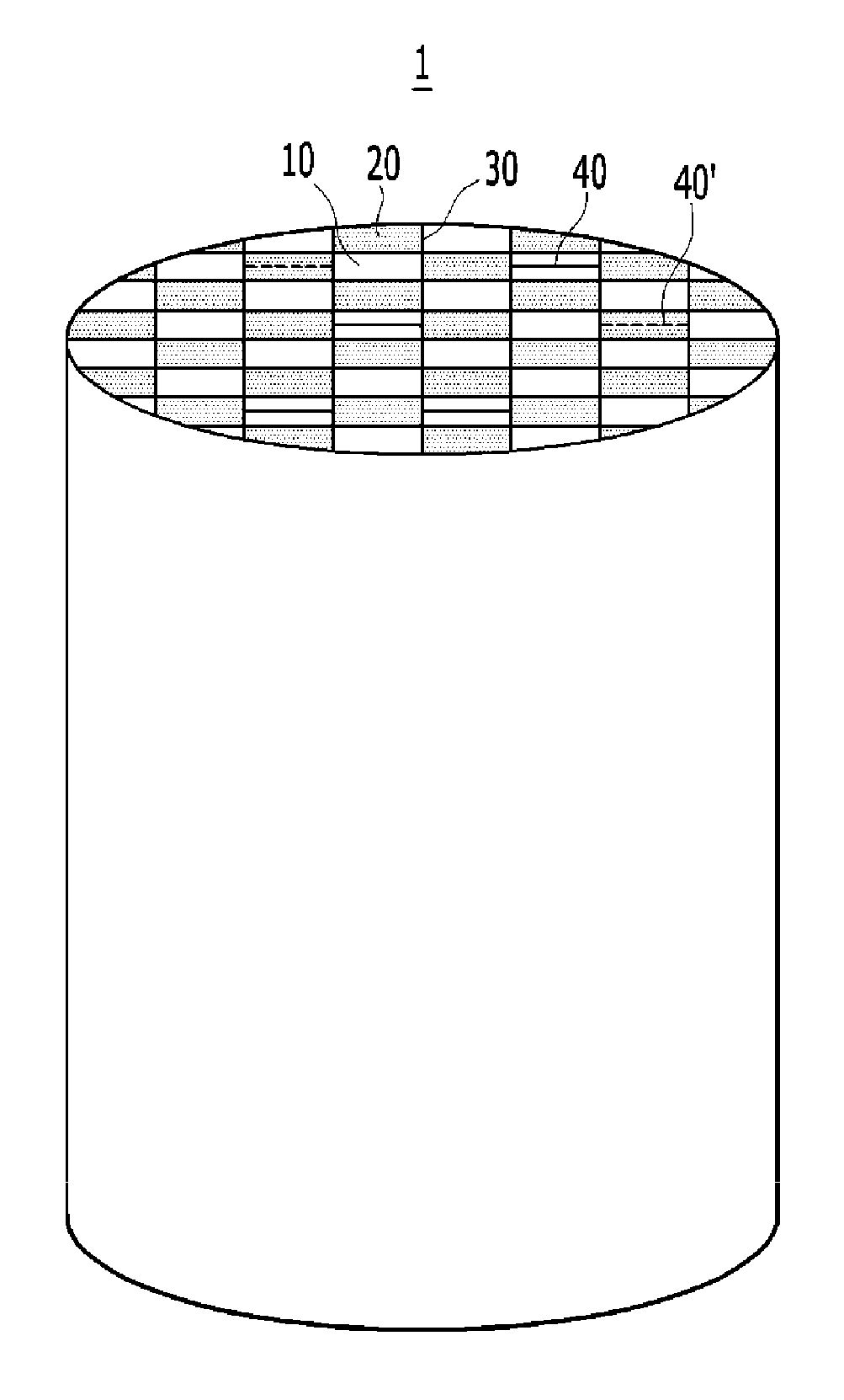
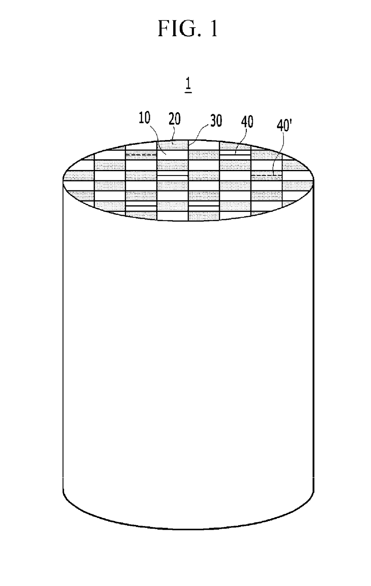
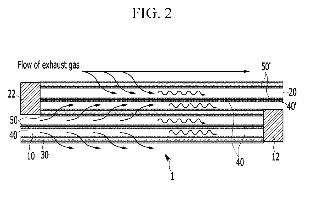
[0051]A catalyzed particulate filter according to an exemplary embodiment of the present invention is configured for use in variety of devices, as well as vehicle, that get energy by burning fo...


PUM

PropertyMeasurementUnit
wall thicknessaaaaaaaaaa

Abstract

A method of manufacturing a catalyzed particulate filter may include: preparing a bare particulate filter; injecting a first catalyst slurry into at least one inlet channel or at least one outlet channel; discharging a portion of the first catalyst slurry by blowing gas into the at least one outlet channel or the at least one inlet channel or drawing the gas from the at least one inlet channel or the at least one outlet channel; injecting a second catalyst slurry into the at least one outlet channel or the at least one inlet channel; discharging a portion of the second catalyst slurry by blowing gas into the at least one inlet channel or the at least one outlet channel or drawing the gas from the at least one outlet channel or the at least one inlet channel; and drying/calcining the particulate filter from which the portion of the first catalyst slurry and the portion of the second catalyst slurry are discharged.

Description

CROSS-REFERENCE TO RELATED APPLICATION[0001]The present application claims priority to and the benefit of Korean Patent Application No. 10-2016-0094296 filed on Jul. 25, 2016, the entire contents of which are incorporated herein by reference.BACKGROUND OF THE INVENTIONField of the Invention[0002]The present invention relates to a method of manufacturing a catalyzed particulate filter. More particularly, the present invention relates to a method of manufacturing a catalyzed particulate filter including at least one porous wall defining a boundary between at least one inlet channel and at least one outlet channel, a first support located within at least one among the at least one inlet channel, and a second support located within at least one among the at least one outlet channel, the method being related to effectively coating a catalyst on the at least one wall and the first and the second supports.Description of Related Art[0003]An exhaust gas from internal combustion engines such ...

Claims


Application Information

Patent Timeline
Patent Type & Authority Applications(United States)
IPC IPC(8): F01N3/035B01J37/02F01N3/28F01N3/022F01N3/08F01N3/20B01D53/94B01J35/04
CPCF01N3/035B01D53/9472B01J37/024B01J37/0236B01J35/04F01N3/0222B01D2255/9202F01N3/0842F01N3/2066F01N3/2882B01D2255/903B01D2255/9155F01N3/0821B01D46/2418B01D53/9418B01D53/9422B01D53/9463F01N2250/02F01N2330/06F01N2330/60F01N2370/02F01N2510/06F01N2510/068F01N2330/30B01D39/14B01D46/0027B01D53/94F01N2330/04
Inventor JUNG, CHANGHOKIM, PYUNG SOON
Owner HYUNDAI MOTOR CO LTD
Why Eureka
Try Eureka