Honeycomb structure

a honeycomb and structure technology, applied in the field of honeycomb structures, can solve the problems of uneven filling of pores with catalysts, large pressure loss, and inability to evenly fill pores of partition walls, etc., to suppress an increase of pressure loss, reduce the number of pores with pore, and increase the filling rate of catalysts

Active Publication Date: 2019-08-29
NGK INSULATORS LTD
View PDF0 Cites 1 Cited by
  • Summary
  • Abstract
  • Description
  • Claims
  • Application Information

AI Technical Summary

Benefits of technology

[0015]The honeycomb structure of the present invention can increase the filling rate of catalysts, which are loaded to purify exhaust gas, into pores of the partition wall and can suppress an increase of a pressure loss after loading with the catalysts to purify exhaust gas. Specifically the honeycomb structure of the present invention reduces the number of pores having pore diameters that are less fillable with catalysts, and so the pores of the partition wall can be easily filled with the catalysts. This can effectively suppress an increase of a pressure loss of the honeycomb structure after loading with the catalysts to purify exhaust gas. In this way, the honeycomb structure can suppress an increase of a pressure loss while increasing the amount of catalysts for loading, for example, and can achieve compatibility between the “improving the purification performance” and “suppressing an increase of a pressure loss”.

Problems solved by technology

When the honeycomb structure with increased porosity of the partition wall is used as a catalyst carrier to be loaded with a catalyst to purify exhaust gas, a problem occurs when the catalyst enters the pore of the partition wall.
For instance, a conventional honeycomb structure with a simply increased porosity of the partition wall has a problem that, when the catalyst particles are coarse or the catalyst slurry has high viscosity, the pores of the partition wall cannot be filled with the catalyst evenly, and so some of the pores are not filled with the catalysts.
Such a honeycomb structure having the pores filled with the catalysts unevenly will have larger pressure loss.

Method used


Image

  • Honeycomb structure
  • Honeycomb structure
  • Honeycomb structure

Examples


first embodiment

(1) Honeycomb Structure (First Embodiment)

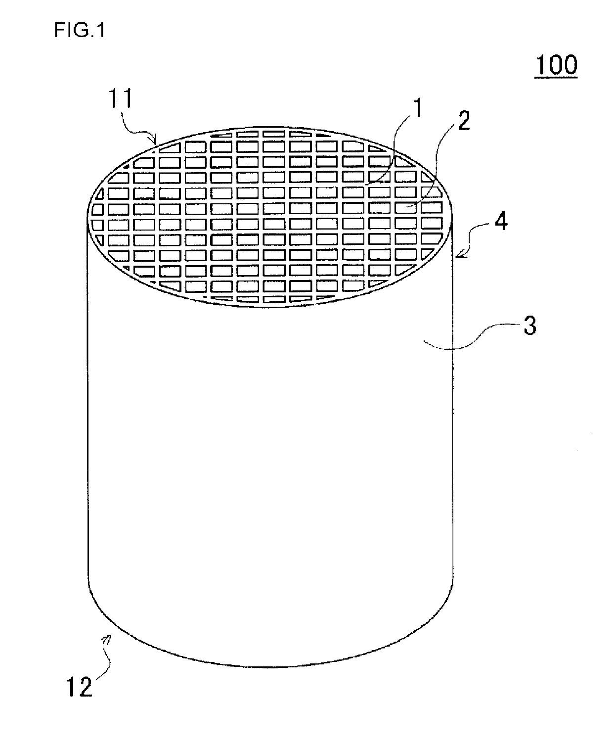
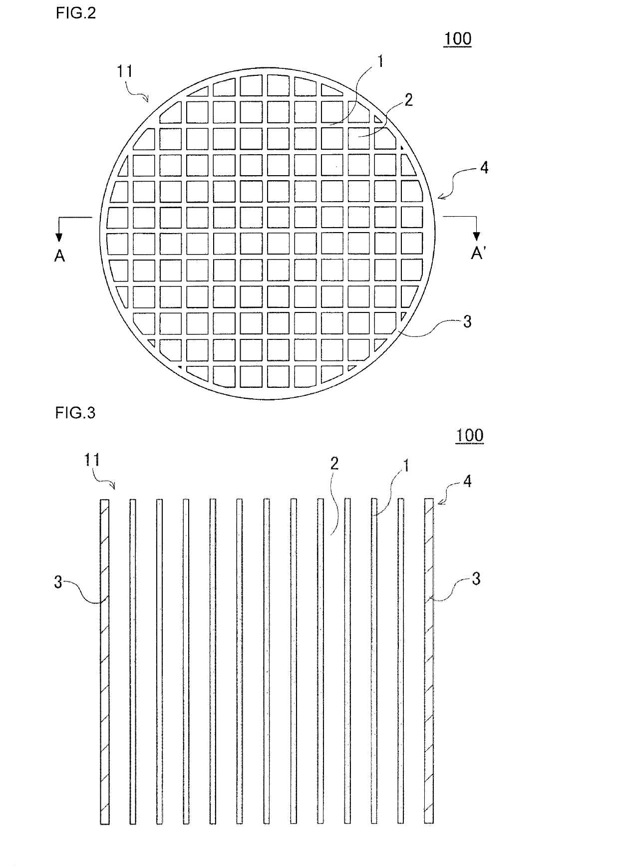
[0023]A first embodiment of the honeycomb structure of the present invention is a honeycomb structure 100 as shown in FIGS. 1 to 3. FIG. 1 is a perspective view schematically showing the first embodiment of the honeycomb structure of the present invention. FIG. 2 is a plan view showing the side of a first end face of the honeycomb structure of FIG. 1. FIG. 3 is a schematic cross-sectional view taken along the line A-A′ of FIG. 2.

[0024]As shown in FIGS. 1 to 3, the honeycomb structure 100 of the present embodiment includes a pillar-shaped honeycomb structure body 4 having a first end face 11 and a second end face. The honeycomb structure body 4 has a porous partition wall 1 that surrounds a plurality of cells 2, and the plurality of cells extends from the first end face 11 to the second end face 12 of the honeycomb structure body and serves as a through channel of fluid. In the honeycomb structure 100 of the present embodiment, the honeycomb ...

second embodiment

(2) Honeycomb Structure (Second Embodiment)

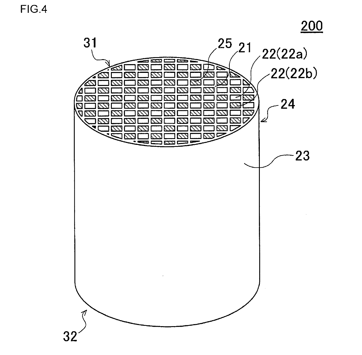
[0041]The following describes a second embodiment of the honeycomb structure of the present invention. The second embodiment of the honeycomb structure of the present invention is a honeycomb structure 200 as shown in FIGS. 4 to 6. FIG. 4 is a perspective view schematically showing the second embodiment of the honeycomb structure of the present invention. FIG. 5 is a plan view showing the side of the first end face of the honeycomb structure of FIG. 4. FIG. 6 is a schematic cross-sectional view taken along the line B-B′ of FIG. 5.

[0042]As shown in FIGS. 4 to 6, the honeycomb structure 200 of the present embodiment is a honeycomb structure 200 including a honeycomb structure body 24 and a plugging portion 25. The honeycomb structure body 24 is a pillar-shaped body including a porous partition wall 21 that surrounds a plurality of cells 22, and the plurality of cells extends from a first end face 31 to a second end face 32 of the honeycomb st...

example 1

[0053]2.5 parts by mass of a pore former, 60 parts by mass of a dispersing medium, and 6 parts by mass of an organic binder were added to 100 parts by mass of the cordierite forming raw material, followed by mixing and kneading to prepare a kneaded material. As the cordierite forming raw material, alumina, aluminum hydroxide, kaolin, talc, and silica were used. As the dispersing medium, water was used. As the organic binder, methylcellulose was used. As the dispersing agent, dextrin was used.

[0054]As the pore former, an water absorptive polymer having the average particle diameter of 20 μm was used. The pore former that has been used showed the following values in the curve indicating the relationship between the particle diameter of the pore former and the cumulative volume (a value obtained by accumulating the volume values of particles having a certain particle diameter or less). More specifically the pore former that has been used showed, in the curve, the particle diameter d90 ...


PUM

PropertyMeasurementUnit
porosityaaaaaaaaaa
pore diameteraaaaaaaaaa
pore diametersaaaaaaaaaa

Abstract

A honeycomb structure, including: a pillar-shaped honeycomb structure body having a first end face and a second end face and including a porous partition wall disposed so as to surround a plurality of cells, the plurality of cells extending from the first end face to the second end face and serving as a through channel of fluid, wherein
    • the partition wall has a porosity of 45 to 65%,
    • the partition wall has an average pore diameter of 15 to 25 μm, and
    • the partition wall has a cumulative pore volume, which is measured by mercury intrusion porosimetry, such that a pore volume ratio of pores having pore diameters of 10 μm or less relative to the overall pore volume of the partition wall is 10% or less, and a pore volume ratio of pores having pore diameters of 40 μm or more is 10% or less.

Description

[0001]The present application is an application based on JP-2018-035467 filed on Feb. 28, 2018 with Japan Patent Office, the entire contents of which are incorporated herein by reference.BACKGROUND OF THE INVENTIONField of the Invention[0002]The present invention relates to honeycomb structures. More particularly, the present invention relates to a honeycomb structure capable of increasing the filling rate of catalyst, which is loaded to purify exhaust gas, into pores of the partition wall and suppressing an increase of pressure loss after loading with the catalyst to purify exhaust gas.Description of the Related Art[0003]Developed countries are examining to further tighten the standards on NOx emission from diesel-fueled vehicles and tracks. To meet such NOx emission standards, various techniques have been proposed to treat NOx in exhaust gas. One of these techniques manufactures a honeycomb structure having a porous partition wall loaded with Selective Catalytic Reduction catalyst...

Claims


Application Information

Patent Timeline
Patent Type & Authority Applications(United States)
IPC IPC(8): B01J35/04B01D53/94B01D46/24B01J35/10B01J37/02B01J37/08B01J29/00F01N3/28
CPCB01J35/04F01N2330/02B01D46/2429B01D46/2474B01D46/247B01J35/1076B01J37/0201B01J37/0236B01J37/08B01J29/00F01N3/281B01D2255/9155B01D2046/2433B01D2046/2437B01D2046/2481B01D53/9431F01N3/2803B01D46/24493B01D46/24492B01D46/2484B01D46/2482B01D46/2476B01D46/24491F01N3/2828F01N3/10F01N3/0222B01J35/023B01J35/1038B01J35/1042B01J37/0018B01J37/0221B01J37/0246B01J37/088Y02T10/12
Inventor YAMAMOTO, HIROTAKA
Owner NGK INSULATORS LTD
Why Eureka
Try Eureka