
Fan assembly

a technology of fan assembly and fan body, which is applied in the direction of liquid fuel engine components, pump components, non-positive displacement fluid engines, etc., can solve the problems of limiting the performance of the fan in terms of maximum pressure and maximum flow, and achieves the effects of reducing power consumption, reducing pressure drop, and increasing efficiency

Inactive Publication Date: 2018-01-25
KONINKLJIJKE PHILIPS NV
View PDF5 Cites 8 Cited by
  • Summary
  • Abstract
  • Description
  • Claims
  • Application Information

AI Technical Summary

Benefits of technology

The present patent is about a fan assembly that improves efficiency and reduces power consumption. The fan assembly includes a housing with air inlet, fan inlet, and air outlet, and an impeller with blades. The assembly also has a filter between the air inlet and the impeller. The fan assembly allows air to have a rotational component as it enters the air inlet and impeller region. Additionally, the housing can have multiple air inlets for increased filter surface and higher inflow. These features enhance the performance and fan assembly's ability to manage airflow.

Problems solved by technology

Applicant has further recognized that the prior art inlet configuration limits the rotational component of the air before it encounters the region of the fan blades, thereby limiting the performance of the fan in terms of maximum pressure as well as maximum flow.

Method used


Image

  • Fan assembly
  • Fan assembly
  • Fan assembly

Examples


Embodiment Construction

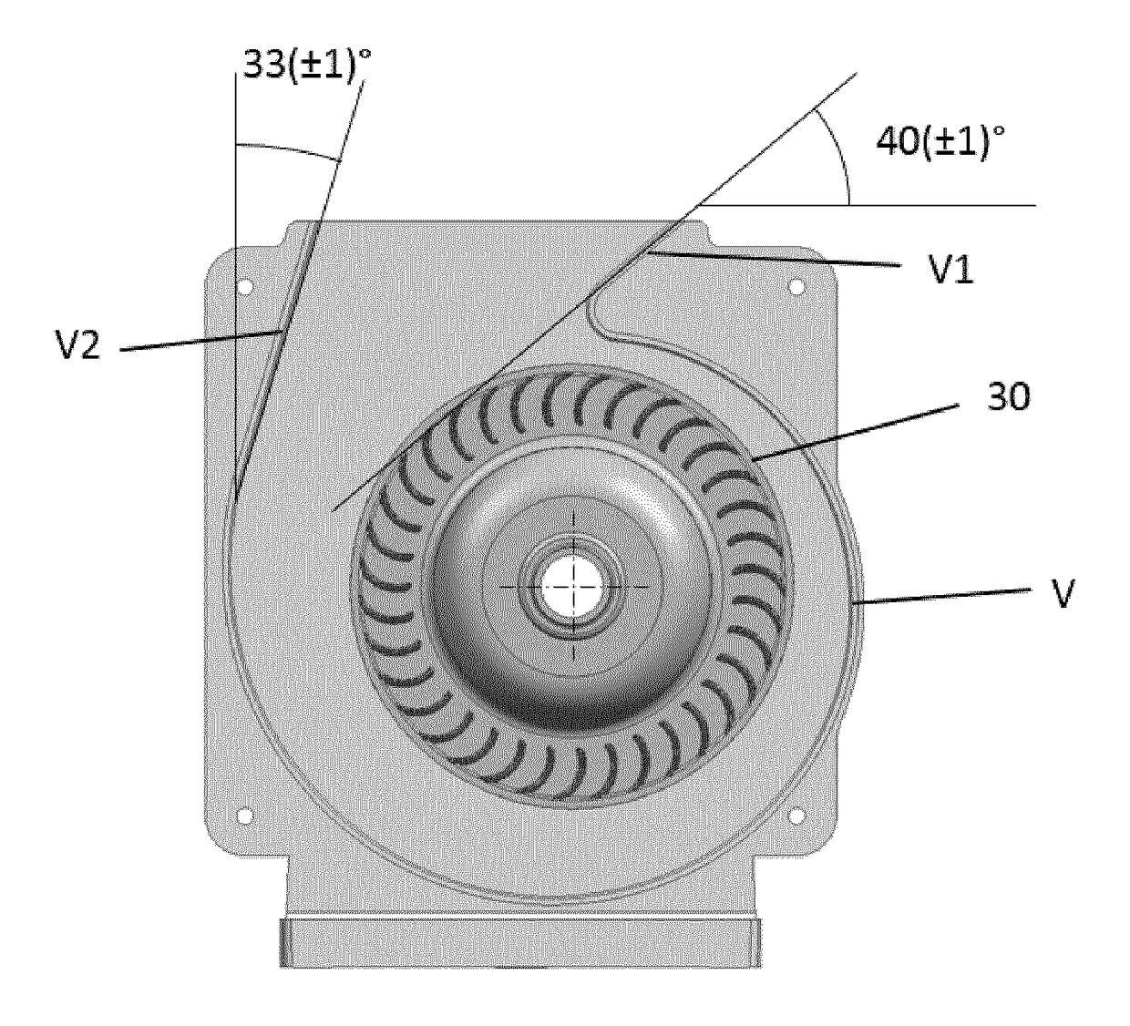
[0028]The present disclosure describes various embodiments of apparatus, systems, devices, and methods for improving the function of a fan assembly. More generally, applicant has recognized and appreciated that it would be beneficial to improve efficiency and reduce power consumption of a fan during operation. A particular goal of utilization of embodiments of the present disclosure is to be able to increase the output of a fan assembly without increasing power consumption.

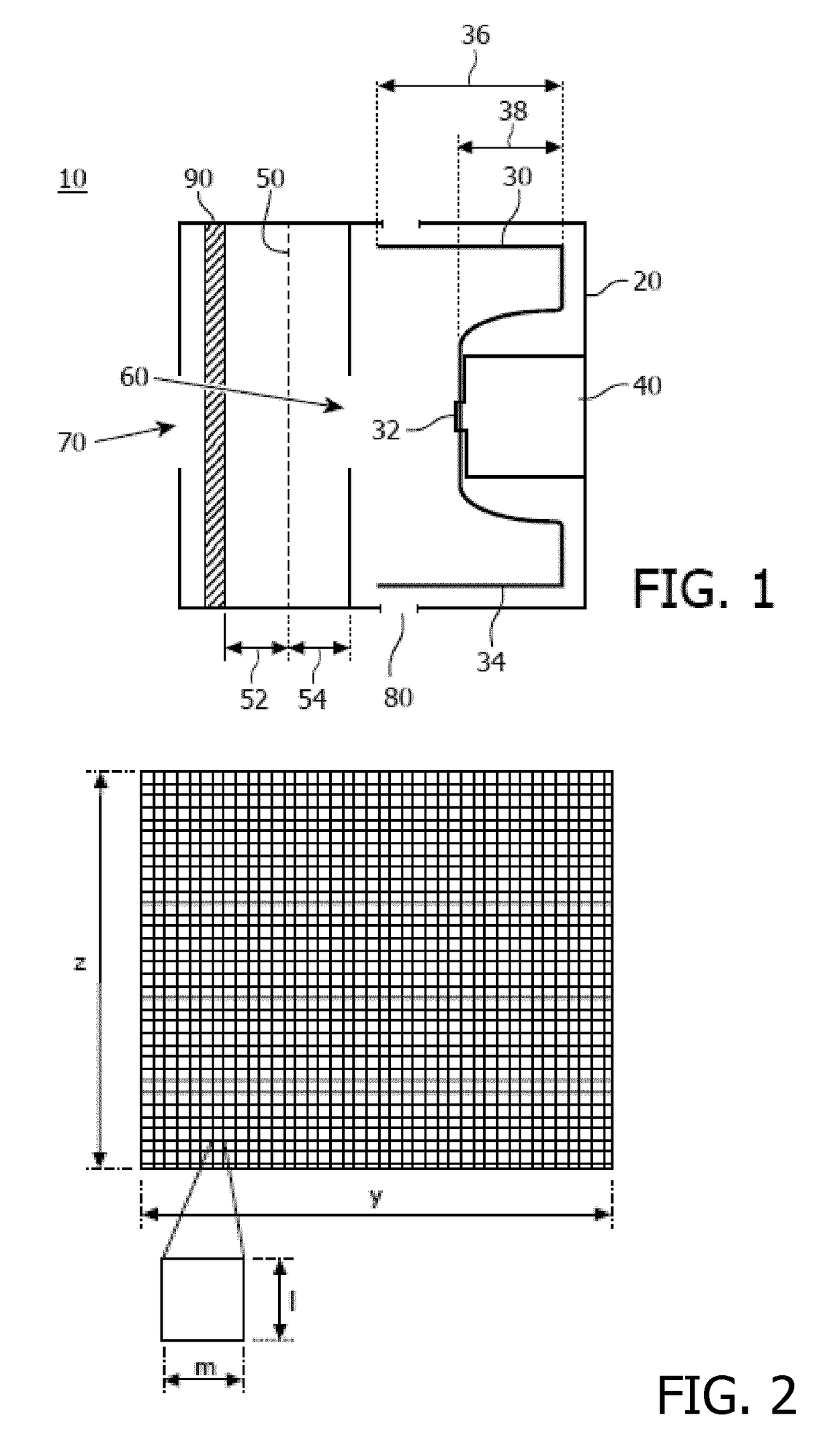
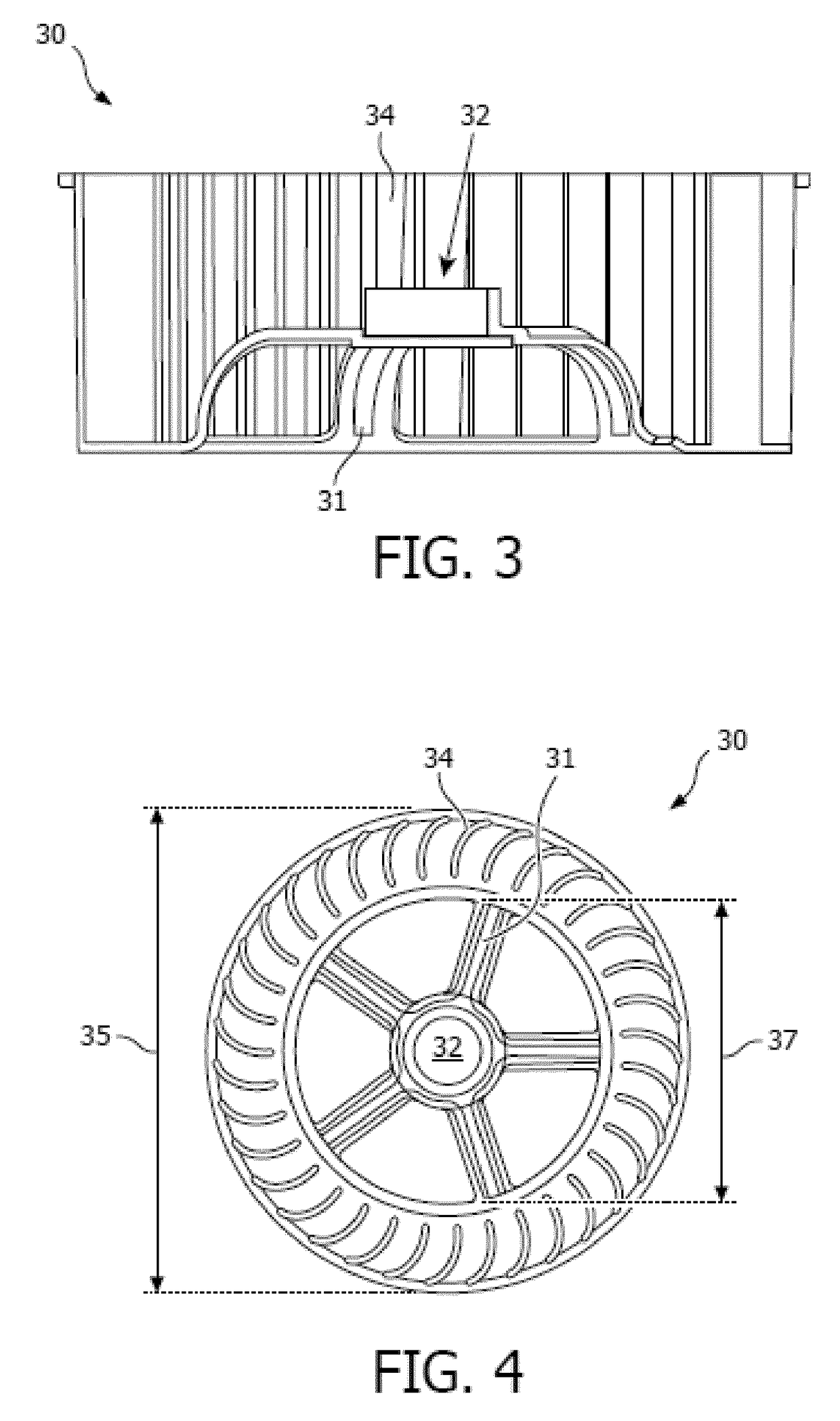
[0029]In view of the foregoing, various embodiments and implementations are directed to a fan assembly with an air-permeable guard positioned between the air inlet and the fan inlet, and spaced a predetermined distance from the fan inlet to allow the incoming air to at least partially rotate prior to entering the fan inlet. The fan assembly also has a radial impeller with a plurality of spaced blades positioned circumferentially around a domed center that faces the fan inlet.

[0030]Referring to FIG. 1, in one embod...


PUM


Abstract

A fan assembly (10) includes a housing (20) with an air inlet (70), a fan inlet (60), and an air outlet (80). The fan assembly further includes an impeller (30) and a motor (40) configured to drive the impeller, the impeller having a plurality of circumferentially positioned spaced blades (34). An air-permeable guard (50) is positioned between the air inlet and the fan inlet to prevent users from touching the impeller (30), and is spaced a first distance (54) from the fan inlet (60), and a second distance from the air inlet (70) so that a filter (90) may be provided between the air inlet (70) and the air-permeable guard (50). Preferably, the first distance (54) is such so as to allow incoming air to at least partially rotate prior to entering the fan inlet. Preferably, the plurality of circumferentially positioned spaced blades (34) is positioned circumferentially around a domed center (32) of the impeller (30), the domed center (32) facing the fan inlet (60), and the domed center (32) co-rotates with the spaced blades (34).

Description

FIELD OF THE INVENTION[0001]The present disclosure is directed generally to a fan assembly that improves efficiency and lowers power consumption.BACKGROUND OF THE INVENTION[0002]Fresh, clean air is one of the most basic needs for human beings. However, air can contain many different kinds of impurities, including particulates, viruses, bacteria, and fungi, all of which can cause or aggravate health issues, illness, and other negative outcomes. In order to improve air quality, there are many different technologies that clean air, the most common of which is an air filter. In general, filters clean air by means of a fan that pushes and / or pulls the air through the filter unit.[0003]In order to push or pull air through an air filter in an air purifying unit there are several different fan types, including radial fans and axial fans. Axial fans generate high flowrates, but result in relatively low maximum pressures. In contrast, radial fans generate relatively high maximum pressures but...

Claims


Application Information

Patent Timeline
Patent Type & Authority Applications(United States)
IPC IPC(8): F04D29/42F04D29/28F04D29/70F04D25/08
CPCF04D29/4226F04D25/08F04D29/283F04D29/703F04D29/282F04D29/4213F04D29/28
Inventor VAN DER KOOI, JOHANNES TSEARDMALTHA, KRIJNDUINEVELD, PAULUS CORNELIS
Owner KONINKLJIJKE PHILIPS NV
Learn More