
Diode light source for a projector

a projector and diode technology, applied in the field of lighting, can solve the problems of projector penalization and large size of light sources, and achieve the effect of high lighting power and simplified light sources

Active Publication Date: 2018-01-25
XYZED
View PDF2 Cites 3 Cited by
  • Summary
  • Abstract
  • Description
  • Claims
  • Application Information

AI Technical Summary

Benefits of technology

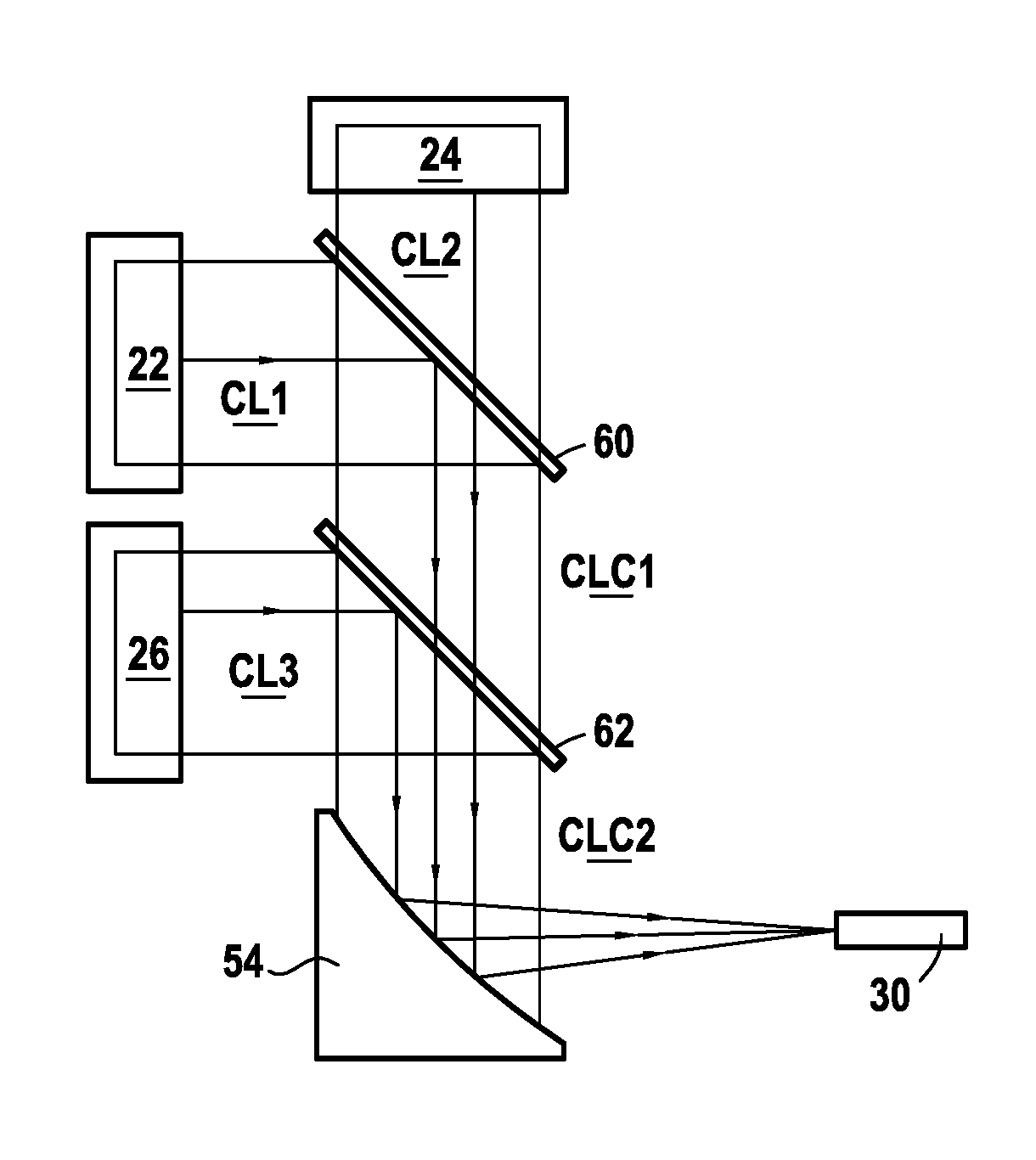
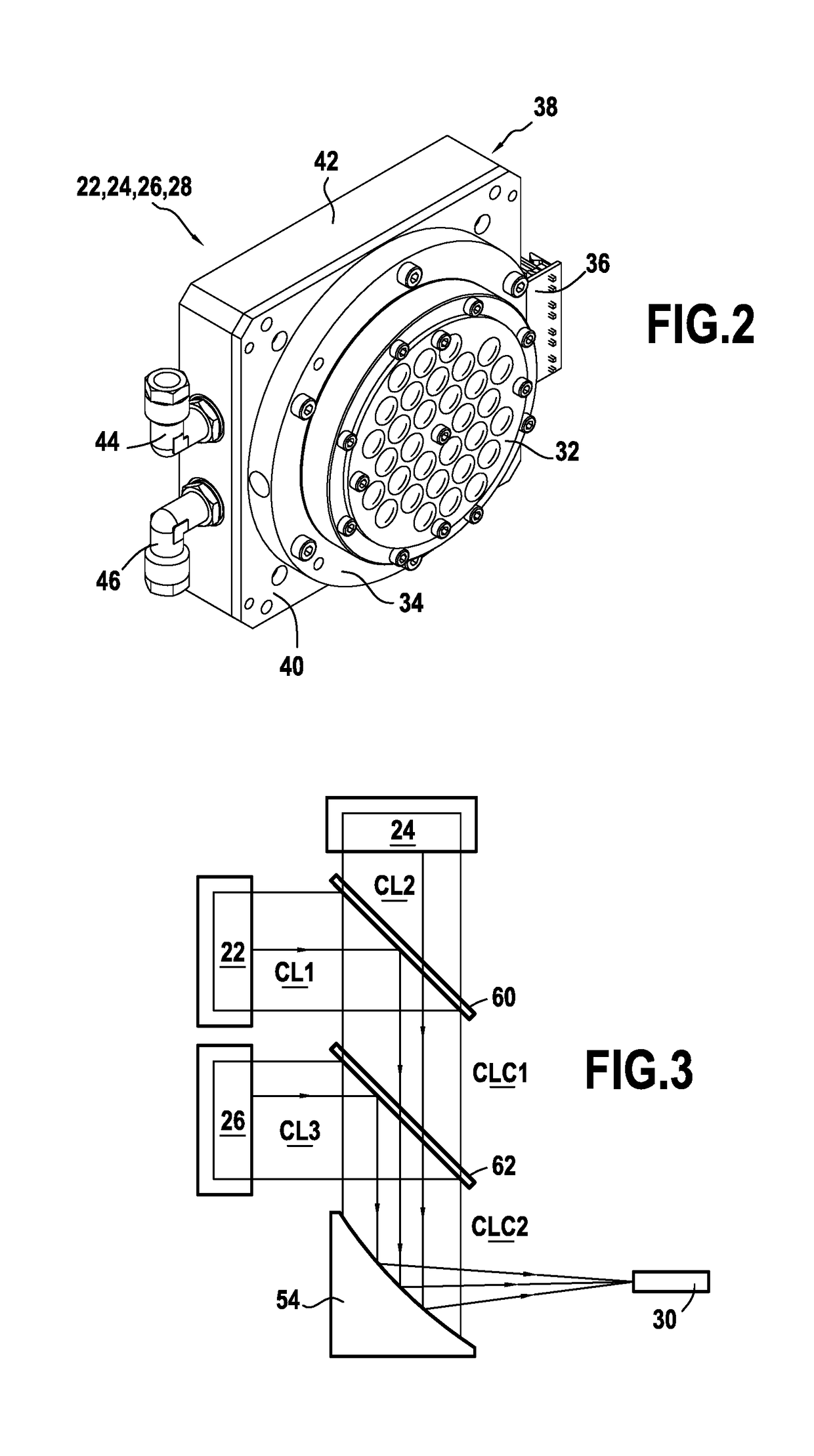
The present invention introduces a lighting projector with a simplified light source. The invention replaces the need for optical fibers to collimate each color and uses dichroic plates to reflect the various light beams onto a single off-axis parabolic mirror. This permits the concentration of all light beams onto a single determined focal point, which is then conveyed to a single optical fiber. The result is a more compact but high-power lighting source that can reach up to 100 W.

Problems solved by technology

Unfortunately, those projectors are penalized by the large size of those light sources, due essentially to the very large number of optical fibers used for collecting the light.
Thus, each RGB module connected to a control card needs to be connected to a fiber, which does not make it easy to multiply the number of modules in order to obtain high lighting power (typically greater than 30 watts (W)) in a volume that is small, easy to access, and above all suitable for easy assembly both in fabrication and for maintenance.

Method used


Image

  • Diode light source for a projector
  • Diode light source for a projector
  • Diode light source for a projector

Examples


Embodiment Construction

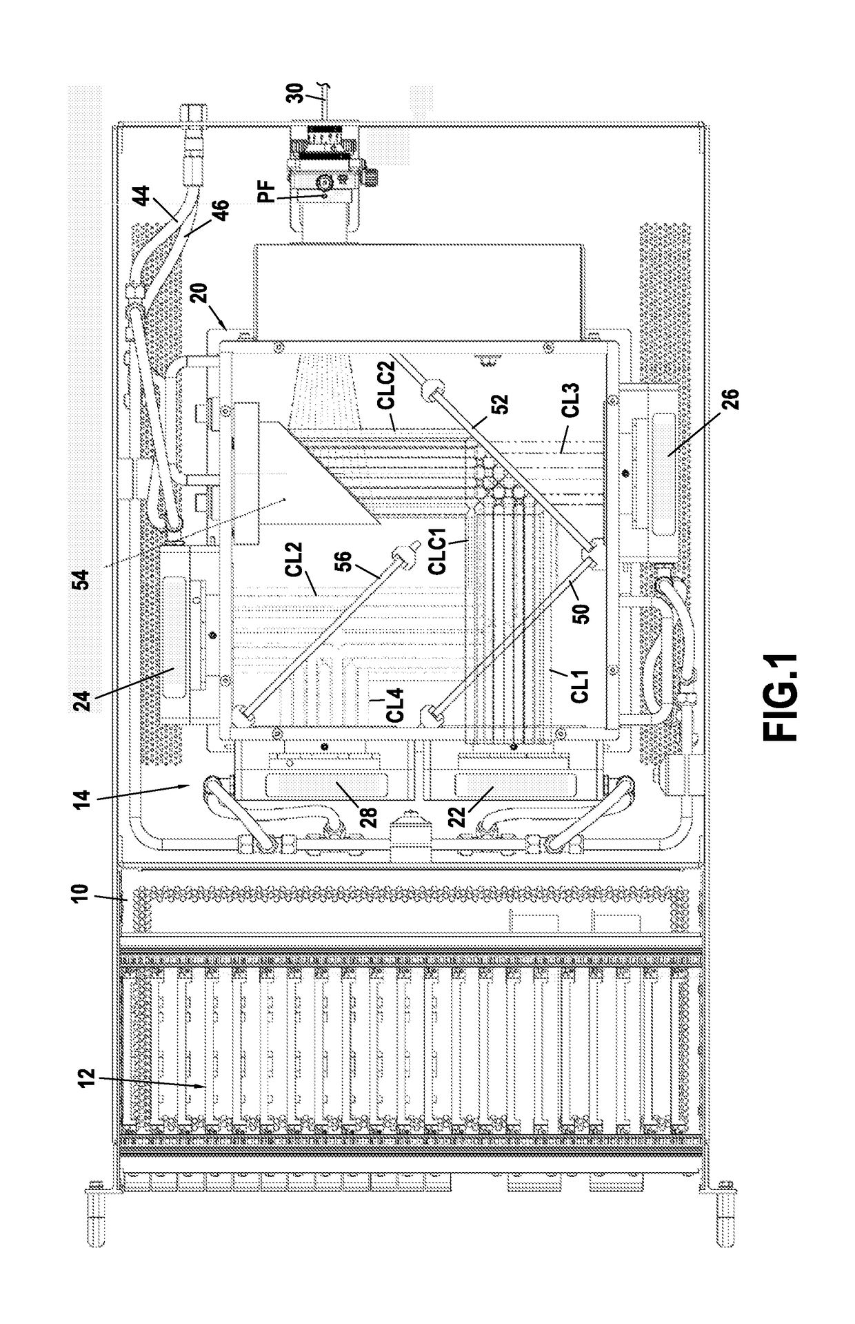
[0022]FIG. 1 shows a diode light source in accordance with the invention for mounting in a standard power supply chassis of the 2U, 3U, or 4U rack type (i.e. suitable for being mounted directly in a standard 19 inch rack). The chassis 10 has an electronic portion 12 that is to receive various cards for controlling diodes and an optical portion 14 designed to receive the light source proper and including means for dissipating the heat given off by the diodes.

[0023]In the invention, the light source 20 is a high power light source that is very compact, being made up from three laser diode lighting modules 22, 24, and 26 arranged at 90° to one another, and from an optical system serving to collimate and focus the light beams coming from these modules into a single outlet optical fiber. Nevertheless, for better color balance, the light source is preferably, but not necessarily, made up from four laser diode modules, the fourth module 28 then advantageously being arranged on the axis of ...


PUM


Abstract

A projector includes a diode light source for a projector. The light source comprises at least first, second, and third diode matrices respectively delivering at least first, second, and third light bundles at separate wavelengths and of determined dimensions. A first dichroic plate forms a first combined light bundle CLC1 from the first and second light bundles, a second dichroic plate forming a second combined light bundle CLC2 from the first combined light bundle and the third light bundle, and an off-axis parabolic mirror for receiving the second combined light bundle CLC2 and focusing it on a determined focal point forming an inlet point for a single optical fiber.

Description

FIELD OF THE INVENTION[0001]The present invention relates to the field of lighting and it relates more particularly to a source of white light for cinema or video projectors using light-emitting diodes (LEDs) or laser diodes.PRIOR ART[0002]Until recently, projectors were conventionally constituted by an incandescent lamp or by a discharge lamp of the xenon, HMI, or HTI type, with a reflector for focusing the light beam coming from the lamp towards an optical system having one or more lenses arranged in the light beam. In spotlights for the stage or spectacles, various shutters are also placed in the outlet from the optical system in order to provide special effects, e.g. an overlay knife, a color wheel, an iris, and a gobo wheel.[0003]Nevertheless, over the last few years, projectors have appeared on the lighting market, in particular for cinema and video, in which the light sources that are to replace such discharge or incandescent lamps are constituted by LEDs or laser diodes, as ...

Claims


Application Information

Patent Timeline
IPC IPC(8): G03B21/20G02B27/14G02B27/10H04N9/31F21V8/00
CPCG03B21/2033H04N9/3167G03B21/2066G03B21/2013G02B6/0006G02B27/1006G02B27/141G03B21/16G02B5/10G03B33/12H04N9/3144H04N9/3164H04N9/3182H01L2924/0002H01L2924/00G02B6/26H01L25/0753
Inventor REBIFFE, MAURICEFERRANDON, JEAN PIERRE
Owner XYZED
Learn More