Measuring system

Active Publication Date: 2018-02-01
TDK MICRONAS GMBH
View PDF6 Cites 3 Cited by
  • Summary
  • Abstract
  • Description
  • Claims
  • Application Information

AI Technical Summary

Benefits of technology

[0027]As the magnitude of the magnetic flux (without an encoder) occurs as an offset in the output signal of the magnetic field sensor, a reduction in the magnetic flux reduces the offset and increases the signal-to-offset ratio significantly. The reduction of the magnetic flux density component in the present case is achieved by more than two magnetic poles.
[0028]An advantage of the device of the invention is that a very good signal-to-offset ratio is achieved with a simple and thus

Problems solved by technology

This package type is not suitable for harsh environments, however, particularly those in an automobile.
This results in a dec

Method used


Image

  • Measuring system
  • Measuring system
  • Measuring system

Examples


Embodiment Construction

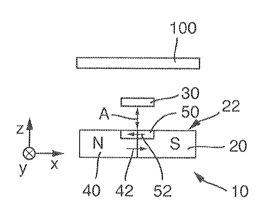
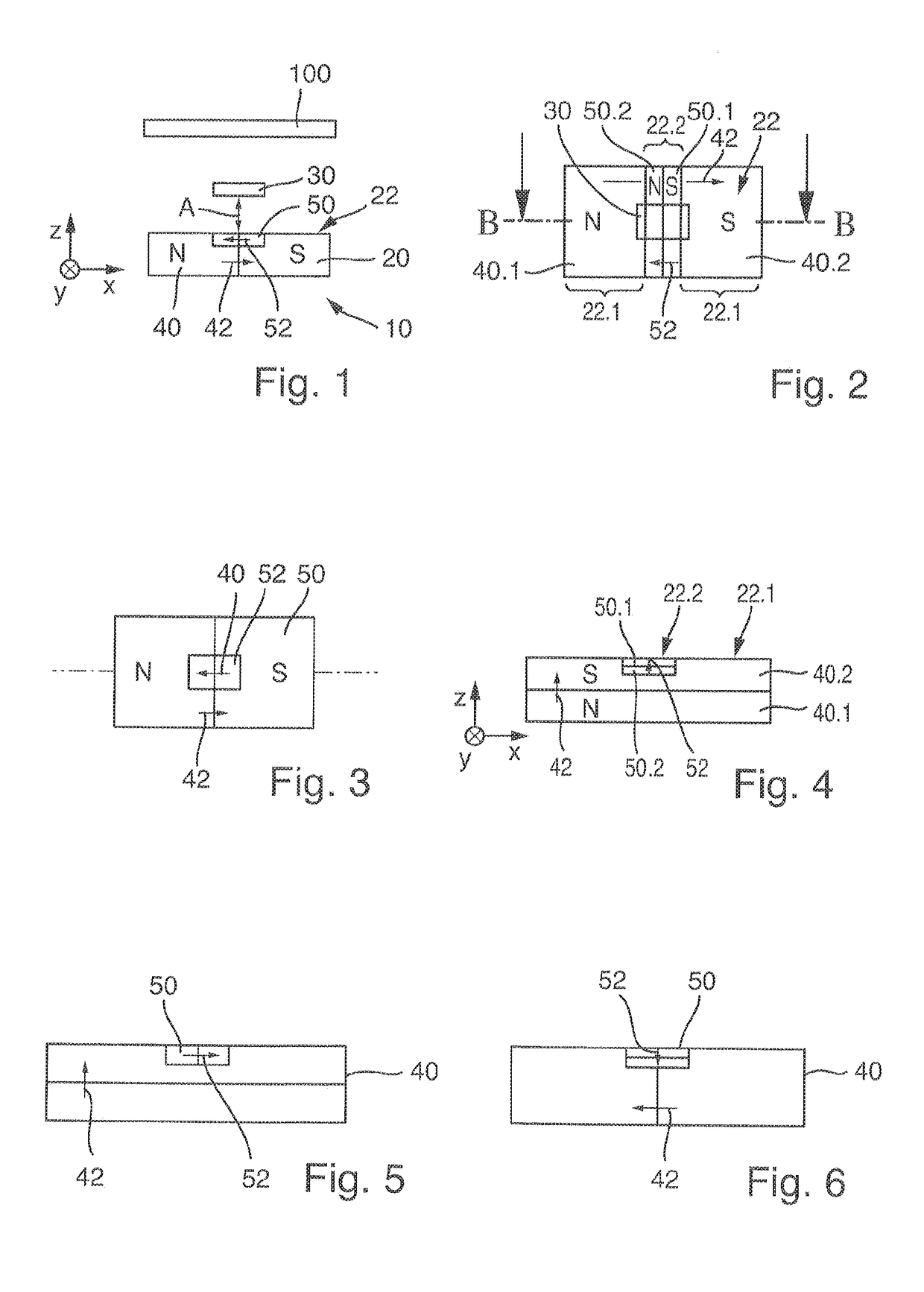
[0055]The illustration in FIG. 1 shows a schematic sectional view of an embodiment of a measuring system 10 of the invention for determining the position of an encoder 100 at least in a first spatial direction.

[0056]FIG. 2 shows a top view of the measuring system from FIG. 1, FIG. 1 corresponding to a sectional view along the straight line B-B from FIG. 2. In addition, a coordinate system with the spatial directions x, y, and z is shown in FIG. 1.

[0057]Measuring system 10 has a magnetic device 20 for generating a magnetic field and a magnetic field sensor 30 for detecting a flux density of the magnetic field at least in a first spatial direction, in the present case in the z-direction.

[0058]Magnetic field sensor 30 is fixedly positioned at a distance A from a top side 22 of magnetic device 20, for example, by plastic by means of a positive connection. Magnetic field sensor 30, for example, a Hall plate, measures the flux density of the magnetic field in a first spatial direction, in...


PUM


Abstract

A measuring system having a magnetic device for generating a magnetic field and at least one magnetic field sensor for detecting a flux density of the magnetic field, at least in a first spatial direction. The magnetic device has a top side facing the magnetic field sensor, the magnetic field sensor is spaced apart from the top side of the magnetic device, the magnetic device has a main magnet, having two poles, with a main magnetizing direction for generating a main magnetic field and at least one secondary magnet, having two poles, with a secondary magnetization direction for generating a secondary magnetic field, the main magnet has larger dimensions than the at least one secondary magnet, the magnetic field is formed by superposition of the main magnetic field and the secondary magnetic field, the secondary magnetic field at least partially compensates the main magnetic field in the first spatial direction.

Description

[0001]This nonprovisional application claims priority under 35 U.S.C. §119(a) to German Patent Application No. 10 2016 009 209.2, which was filed in Germany on Aug. 1, 2016, and which is herein incorporated by reference.BACKGROUND OF THE INVENTIONField of the Invention[0002]The present invention relates to a measuring system.Description of the Background Art[0003]WO 2010 / 060607 A2 discloses an IC package with a semiconductor chip with an integrated circuit and an integrated magnetic sensor. A permanent magnet, whose magnetic flux penetrates the sensor, is spaced apart from the semiconductor chip package. If an object to be measured approaches the head end of the semiconductor chip, the magnetic flux density through the sensor changes.[0004]U.S. Pat. No. 7,250,760 B2 discloses integrated magnetic Hall sensors in which a permanent magnet with the sensor is disposed in the IC package. In this case, the Hall sensors are arranged relative to the field of the permanent magnet such that a ...

Claims


Application Information

Patent Timeline
IPC IPC(8): G01R33/00G01R33/38G01R33/038
CPCG01R33/0005G01R33/0011G01R33/3802G01R33/0082G01R33/038G01R33/0047G01R33/072G01R33/02G01R33/07G01D5/145G01B7/023
Inventor KAUFMANN, TIMOFRANKE, JOERG
Owner TDK MICRONAS GMBH
Why Eureka
Try Eureka