Piston assembly

a technology of pistons and cylinders, applied in the direction of piston rings, mechanical devices, engine components, etc., can solve the problems affecting the oil control function and the pressure of the oil ring on the cylinder wall surface cannot be reduced beyond a certain limit, so as to achieve the effect of reducing the friction resistan

Active Publication Date: 2018-02-08
HONDA MOTOR CO LTD
View PDF0 Cites 2 Cited by
  • Summary
  • Abstract
  • Description
  • Claims
  • Application Information

AI Technical Summary

Benefits of technology

[0005]In view of such problems of the prior art, a primary object of the present invention is to provide an oil ring that can minimize the frictional resistance without impairing the oil control function such as the scraping of lubricating oil from the cylinder wall surface by the oil ring.
[0007]In this arrangement, because the outer peripheral surface of the upper side rail is slanted by the first slant angle θ1 and the outer peripheral surface of the lower side rail is slanted by the second slant angle θ2, during the upward stroke of the piston, each side rail is subjected to a lift that moves the side rail away from the cylinder wall surface owing to a relatively thick buildup of lubricating oil between the outer peripheral surface of the side rail and the cylinder wall surface. Thereby, the lubricating oil is not excessively scraped off the cylinder wall by the oil ring, and hence the shear resistance of the lubricating oil can be reduced. Meanwhile, during the downward stroke of the piston, because very little wedge effect is produced between the outer peripheral surfaces of the two side rails and the cylinder wall surface, the lubricating oil is scraped off the cylinder wall surface in an effective manner and the thickness of the oil film is appropriately controlled. During the upward stroke of the piston, owing to the presence of a clearance between the oil ring and the oil ring groove and the compressive deformation of the expander, the upper side rail tilts radially outward (the inner peripheral part thereof is raised in comparison with the outer peripheral part thereof). Therefore, during the upward stroke of the piston, the effective slant angle of the outer peripheral surface is reduced from the first slant angle by this tilting action. However, according to the present invention, because the first slant angle is originally greater than the second slant angle, this tilting action causes the actual slant angle of the outer peripheral surface of the upper side rail to be reduced from the first slant angle to a value closer to the second slant angle. Therefore, both the upper and lower side rails are allowed to engage the cylinder wall surface with an optimum slant angle which may be approximately equal to the second slant angle.
[0009]Thus, the tilt angle that is caused during the upward stroke of the piston can be accurately controlled by determining the size of the clearance and the resiliency of the expander.
[0013]An oil ring configured as discussed above can minimize frictional resistance without impairing the function to control the oil film thickness.

Problems solved by technology

The frictional resistance may be reduced by decreasing the pressure exerted on the cylinder wall surface by the oil ring, but it may impair the oil control function of the oil ring such as the scraping of the lubricating oil off the cylinder wall surface.
Therefore, the pressure of the oil ring on the cylinder wall surface cannot be reduced beyond a certain limit.

Method used


Image

  • Piston assembly
  • Piston assembly
  • Piston assembly

Examples


Embodiment Construction

)

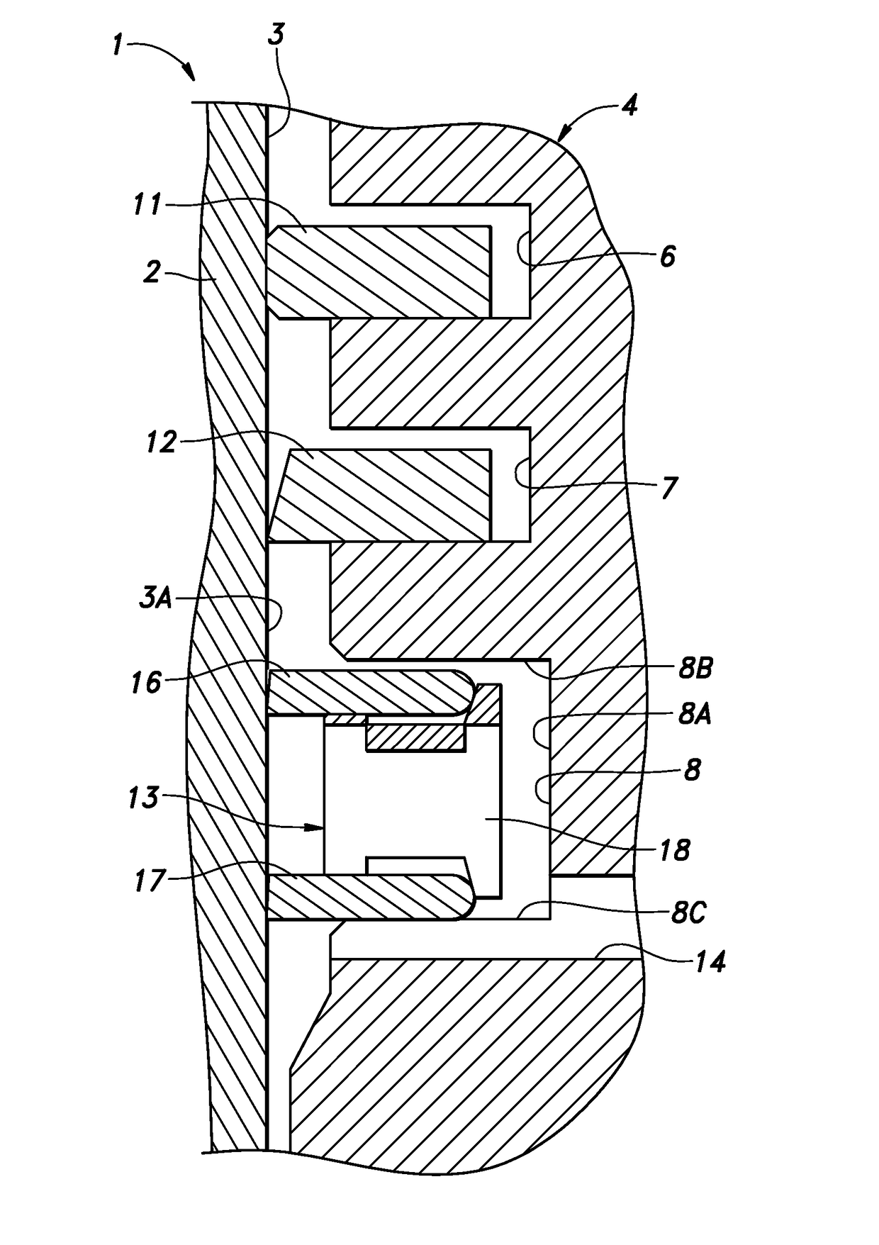
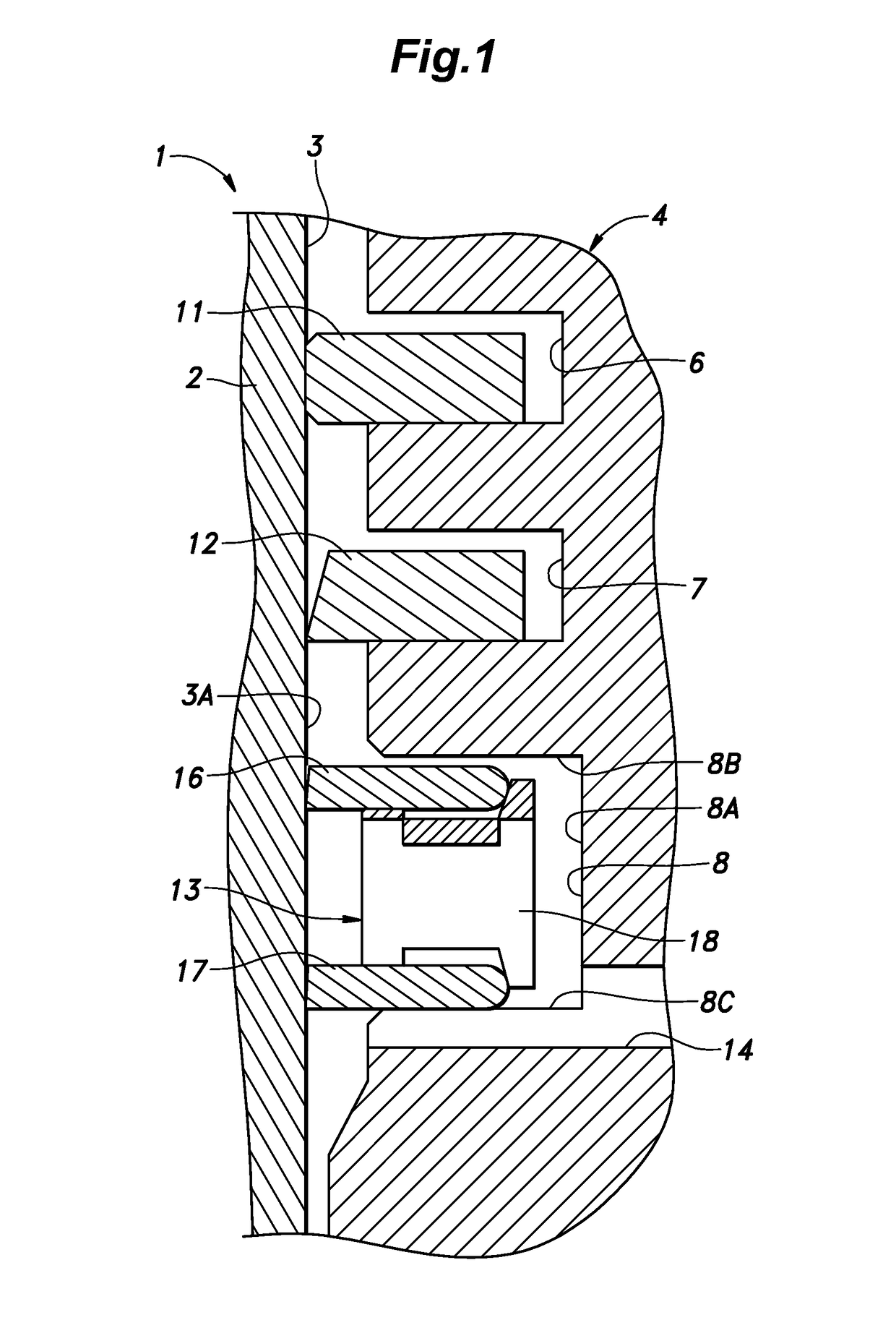
[0024]An oil ring embodying the present invention is described in the following with reference to FIG. 1.

[0025]As shown in FIG. 1, a cylinder block 2 of an internal combustion engine 1 is provided with a cylinder 3 having a circular cross section and extending along a prescribed axial line (which is assumed to be extending vertically for the convenience of description), and a piston 4 is slidably received in the cylinder 3. A combustion chamber is defined by an upper part of the cylinder 3, the top surface of the piston 4 and a cylinder head not shown in the drawing. The outer peripheral part of the piston 4 is formed with a first ring groove 6, a second ring groove 7 and a third ring groove 8, in that order from the top. Each of these ring grooves is annular in shape. The first ring groove 6 and the second ring groove 7 receive a first pressure ring 11 and a second pressure ring 12, respectively, and the third ring groove 8 receives an oil ring 13.

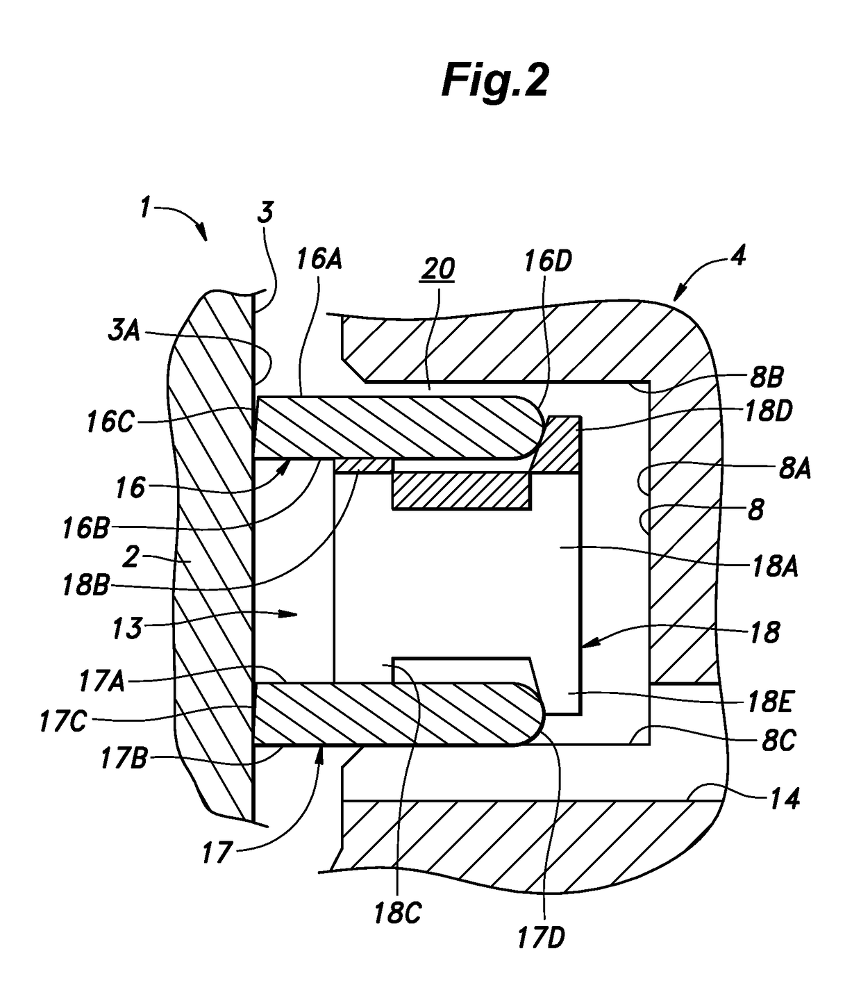
[0026]The third ring groove 8 inc...


PUM


Abstract

Provided is an oil ring (13) for a piston assembly that can minimize the frictional resistance without impairing the oil control function such as the scraping of lubricating oil from the cylinder wall surface by the oil ring. The oil ring consists of an upper side rail (16), a lower side rail (17) and an annular expander (18) interposed between the two side rails, and is received in an oil ring groove (8) with a prescribed vertical clearance (20) that permits tilting of the side rails. An outer peripheral surface (16E, 17E) of each side rail is provided with a radially inward slant. Therefore, during the upward stroke of the piston, the upper side rail tilts in the radially outward direction so that the effective slant angle of the outer peripheral surface of the upper side ring is adjusted to an optimum value.

Description

CROSS-REFERENCE TO RELATED APPLICATIONS[0001]This application is a Continuation of U.S. patent application Ser. No. 15 / 334,362, filed Oct. 26, 2016, which claims the benefit of priority to Japanese Patent Application No. 2015-253302, filed Dec. 25, 2015, the entire contents of which are hereby expressly incorporated by reference in their entirety.TECHNICAL FIELD[0002]The present invention relates to an oil ring for a piston of a reciprocating machine such as an internal combustion engine, and in particular to a composite oil ring including a pair of side rails and an expander interposed between the two side rails and a piston assembly having such an oil ring.BACKGROUND ART[0003]The oil ring used in the pistons of conventional reciprocating internal combustions typically consists of a three piece oil ring including a pair of annular side rails positioned one above the other and a space expander interposed between the two side rails. See JP2003-194222A, for instance.[0004]In recent ye...

Claims


Application Information

Patent Timeline
Patent Type & Authority Applications(United States)
IPC IPC(8): F16J9/20
CPCF16J9/206F16J9/066F16J9/203
Inventor KAWASE, NAOKAZUNAKAGAWA, HAJIME
Owner HONDA MOTOR CO LTD
Why Eureka
Try Eureka