
Apparatus and method for diagnosing failure of sensor

a sensor and apparatus technology, applied in the direction of pressure difference measurement between multiple valves, electric control, instruments, etc., can solve the problems of damage to the engine, inability to correctly control the egr ratio, and difficulty in verifying the reliability of the signal of the differential pressure sensor

Inactive Publication Date: 2018-02-08
HYUNDAI MOTOR CO LTD
View PDF14 Cites 11 Cited by
  • Summary
  • Abstract
  • Description
  • Claims
  • Application Information

AI Technical Summary

Benefits of technology

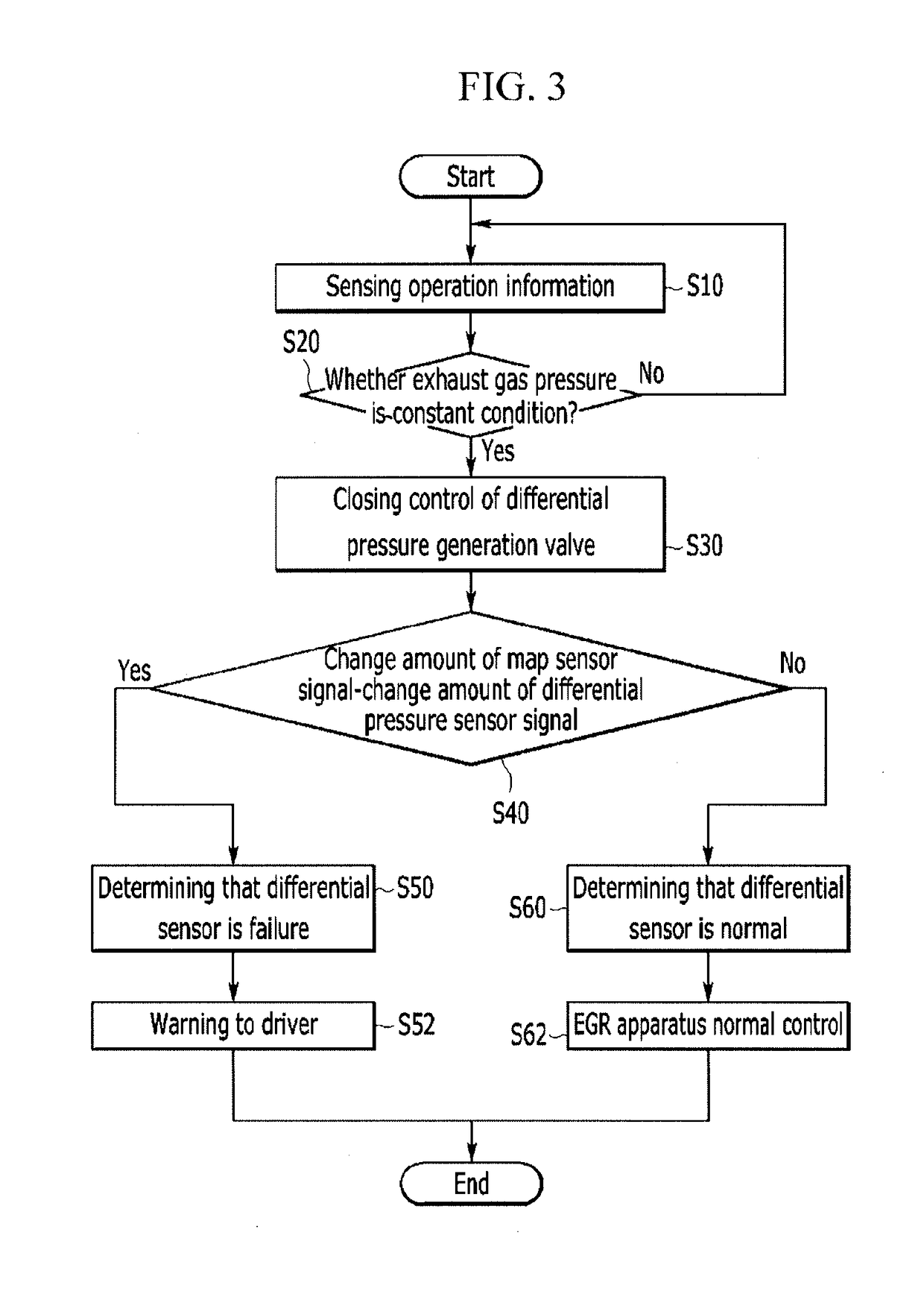
The apparatus and method described in this patent diagnose the failure of a differential pressure sensor by comparing the change in its signal with the change in the manifold absolute pressure (MAP) sensor signal, when the exhaust gas pressure is constant. This helps to identify when the differential pressure sensor is failing and take appropriate action to address it.

Problems solved by technology

In the exhaust gas recirculation system, a differential pressure sensor detecting a pressure difference between a front end portion and a rear end portion of an EGR valve controlling the recirculation gas amount is provided, and when an error is generated in a signal of the differential pressure sensor, it is impossible to correctly control an EGR ratio such that damage may be generated in the engine.
Also, in the exhaust gas recirculation system, because the differential pressure of the front end portion and the rear end portion of the EGR valve is different for each operation region of the engine, it is difficult to verify reliability of the signal of the differential pressure sensor.

Method used


Image

  • Apparatus and method for diagnosing failure of sensor
  • Apparatus and method for diagnosing failure of sensor
  • Apparatus and method for diagnosing failure of sensor

Examples


Embodiment Construction

[0032]Reference will now be made in detail to various embodiments of the present invention(s), examples of which are illustrated in the accompanying drawings and described below. While the invention(s) will be described in conjunction with exemplary embodiments, it will be understood that the present description is not intended to limit the invention(s) to those exemplary embodiments. On the contrary, the invention(s) is / are intended to cover not only the exemplary embodiments, but also various alternatives, modifications, equivalents and other embodiments, which may be included within the spirit and scope of the invention as defined by the appended claims.

[0033]In order to clarify the present invention, parts that are not connected with the description will be omitted, and the same elements or equivalents are referred to by the same reference numerals throughout the specification.

[0034]The size and thickness of each element are arbitrarily shown in the drawings, and the present inv...


PUM


Abstract

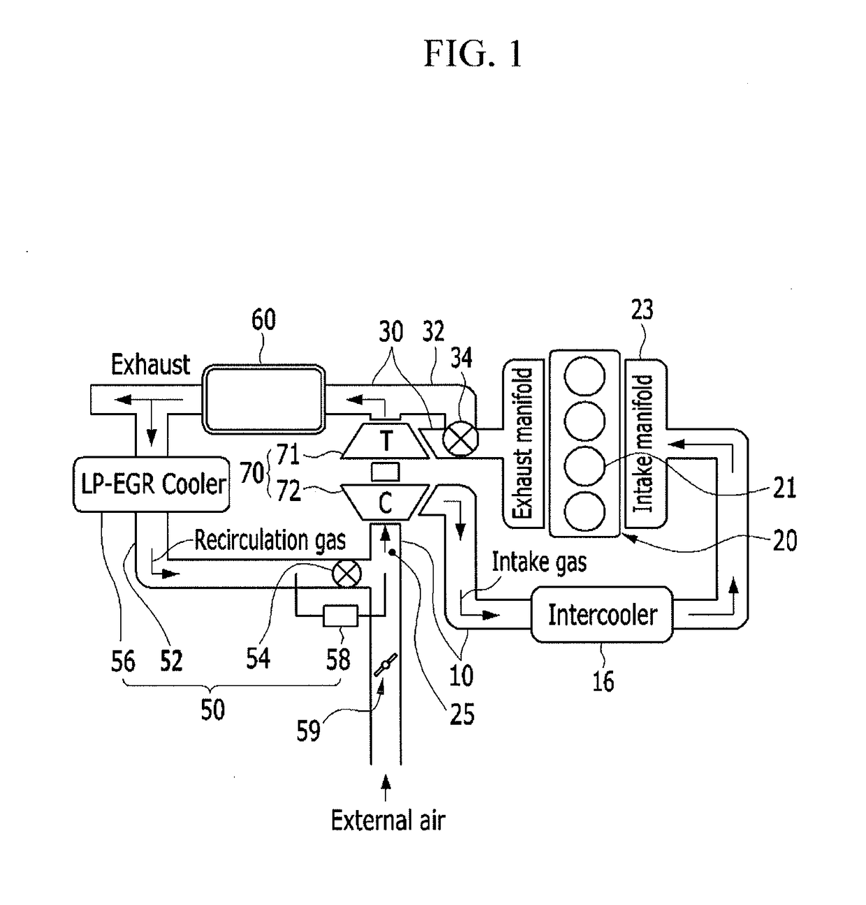
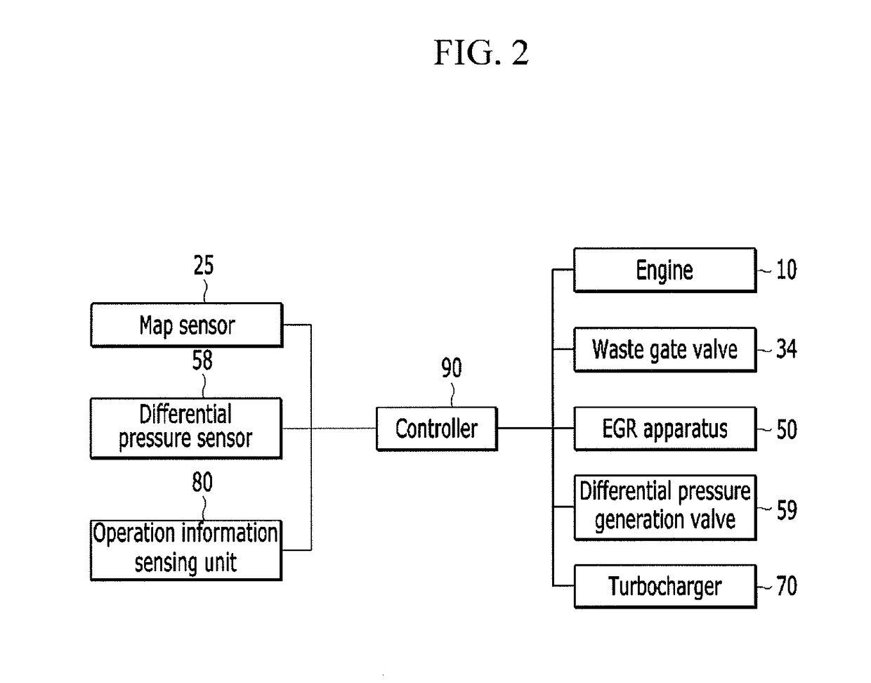
An apparatus for diagnosing a failure of a sensor may include an engine; an intake manifold; a turbocharger including a turbine rotated by exhaust gas of the combustion chamber and a compressor provided at the intake line, rotated in connection with the turbine, and compressing external air; a map sensor measuring a pressure of a front end portion of the compressor; a differential pressure sensor measuring a differential pressure of front and rear end portions of an EGR valve provided at an EGR apparatus; an operation information detecting device measuring operation information including an engine speed and a load; and a controller determining whether an exhaust gas pressure is constant from the operation information and comparing a change amount of the differential pressure sensor signal and a change amount of the map sensor signal in the condition that the exhaust gas pressure is constant to diagnose a failure of the differential pressure sensor.

Description

CROSS-REFERENCE TO RELATED APPLICATION[0001]The present application claims priority to Korean Patent Application No. 10-2016-0099033 filed on Aug. 3, 2016, the entire contents of which is incorporated herein for all purposes by this reference.BACKGROUND OF THE INVENTIONField of the Invention[0002]The present invention relates to an apparatus and a method for diagnosing a failure of a sensor. More particularly, the present invention relates to an apparatus and a method for diagnosing a failure of a differential pressure sensor measuring a differential pressure of a front end portion and a rear end portion of an exhaust gas recirculation (EGR) valve.Description of Related Art[0003]An engine of a vehicle combusts a mixture of air inflowing from the outside and a fuel with an appropriate ratio to generate power.[0004]In a process of generating the power by driving of the engine, the external air for combustion must be appropriately supplied to obtain a desired output and combustion effi...

Claims


Application Information

Patent Timeline
IPC IPC(8): G01L27/00G01L13/00G01M15/10
CPCG01L27/007G01L13/00G01M15/106F02M26/06F02M26/47F02M26/49F02D41/0047F02D41/222F02M26/04G01L13/06
Inventor CHOI, CHOO SAENG
Owner HYUNDAI MOTOR CO LTD
Learn More