
Combine Harvester Improvement

a combine harvester and sensor technology, applied in the field of combine harvesters, can solve the problems of poor instantaneous accuracy poor precision of prior art installations of grain mass flow sensors used in conjunction with grain elevators,

Active Publication Date: 2018-02-15
BLUE LEAF I P INC
View PDF0 Cites 13 Cited by
  • Summary
  • Abstract
  • Description
  • Claims
  • Application Information

AI Technical Summary

Benefits of technology

The present invention is a more accurate and reliable device for measuring the mass flow of grain. It is able to measure the grain flow accurately and precisely without the need for calibration at different grain mass flow rates or moisture contents. The device is also more robust and easy to assemble and maintain. Additionally, it functions independently of the frictional properties of the crop material. Thus, the invention provides a more efficient and accurate means for measuring grain flow in harsh environments.

Problems solved by technology

Various difficulties arise from the use of a sensor plate type grain mass flow sensor.
Prior art installations of grain mass flow sensors used in conjunction with grain elevators suffered further from the fact that grain flow proceeding from the grain elevator exit often did so in a relatively uncontrolled fashion.
Prior art installations of grain mass flow sensors also tended to produce imprecise results due to the variation in bulk properties of the grain, due to changes in incline of the combine, due to vibration, due to drift of the load cell output, and due to the high range of measurements involved.
Certain prior art references have addressed one or more of these problems individually, but none have fully addressed all of the problems.
However, the sensors used are torsional in nature, relying on springs or counterweights to provide the reaction force and upon a tangential displacement sensor.
Such torsional arrangements have been determined not to be sufficiently robust to endure the harsh environment, and are susceptible to greater output variation due to changes in incline or vibrations, which must be compensated to a greater degree using inclinometers.
However, U.S. Pat. No. 5,343,761 does not compensate for variations in the frictional properties of the grain except by use of a non-linear calibration for various grain types and moisture.
However, it makes no provision for compensation in the frictional properties of the grain, except for a complicated calibration routine using empirical test weights, multipliers, and offsets.
Additionally, the measuring accomplished by the sensor plate arrangement in E.P. Patent No. 2,742,324 all takes place over an arc of about 15 to 30 degrees, which limits accuracy.
However, E.P. Patent No. 1,169,905 still used a torsional sensor, which the present inventors have found to be insufficiently robust and susceptible to inaccuracy under certain conditions.
Specifically, the use of a counterweight to balance the tare weight of the sensor plate tends to make the sensor mechanism heavier, so that it cannot react as quickly to changes in the force being applied to the sensor plate, and so that heavier bracketry is required to support the grain mass flow sensor assembly.
Further, while a counterweight arrangement of this type may cancel out the effect of incline or slope angle, it inherently makes the output signal more susceptible to errors due to increased overall tare weight of the measurement mechanism reacting to lateral or longitudinal accelerations of the overall system, for example as the upper part of the combine moves sideways as the combine rolls back and forth about its longitudinal center of gravity over uneven ground.
However, using the tension of the belt driving the grain elevator to determine the mass of grain being lifted is further susceptible to effects from the bulk properties of the grain such as friction and cohesiveness, for example as the grain elevator paddles engage the accumulated mass of grain at the bottom of the grain elevator.

Method used


Image

  • Combine Harvester Improvement
  • Combine Harvester Improvement
  • Combine Harvester Improvement

Examples


Embodiment Construction

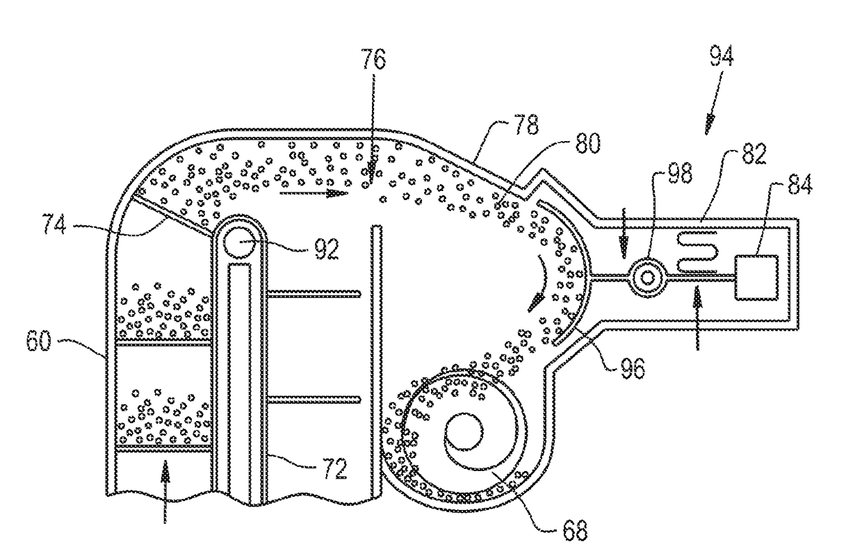
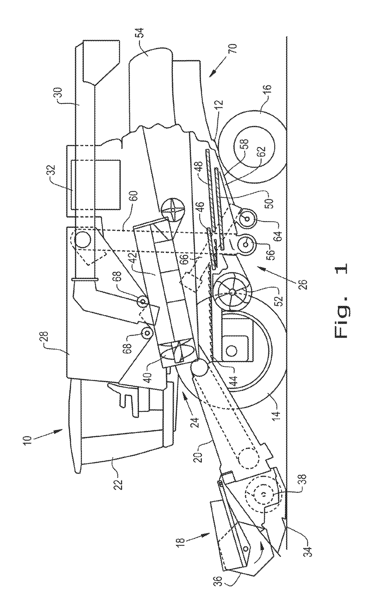
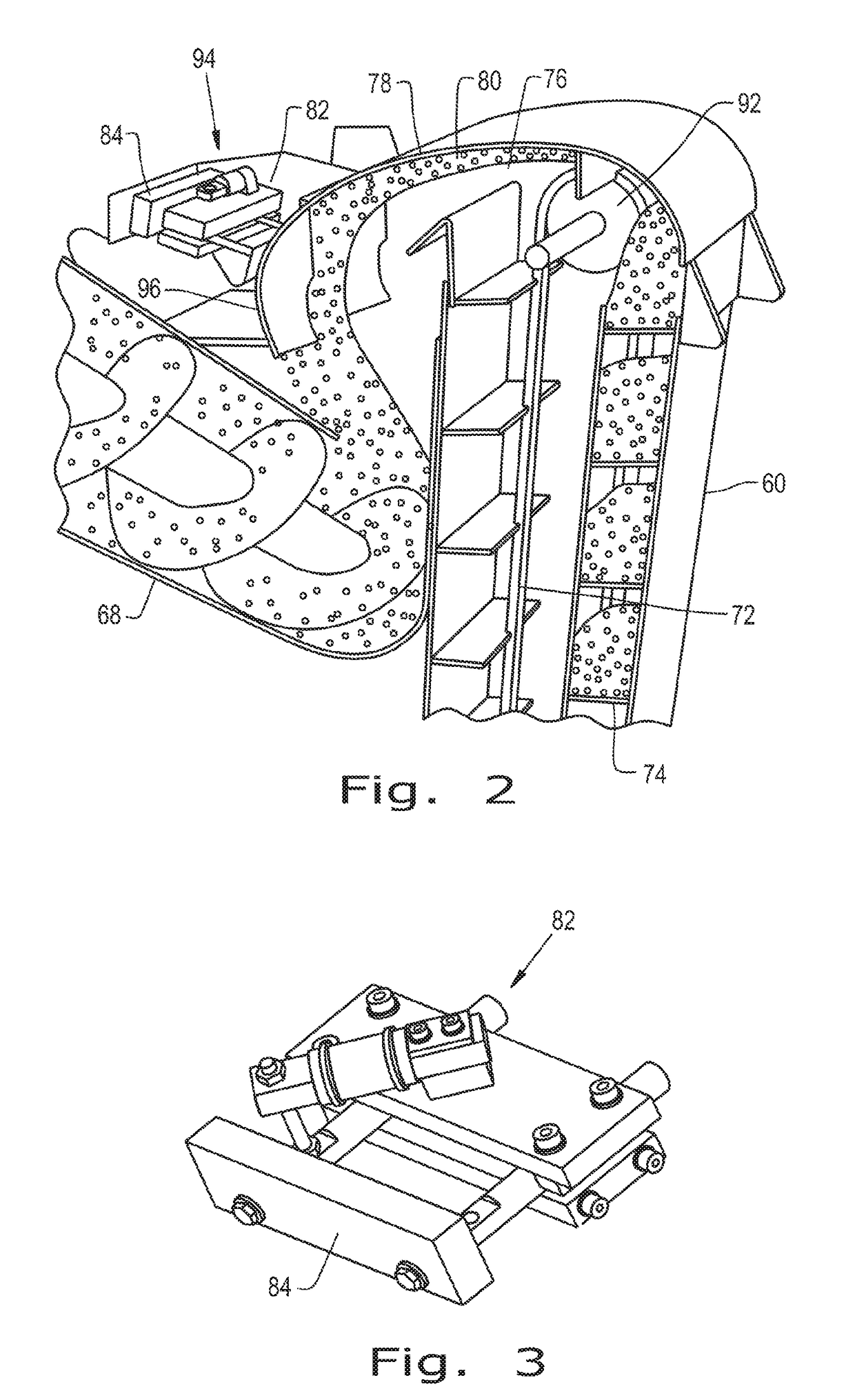
[0045]The terms “grain”, “straw” and “tailings” are used principally throughout this specification for convenience but it is to be understood that these terms are not intended to be limiting. Thus “grain” refers to that part of the crop material that is threshed and separated from the discardable part of the crop material, which is referred to as non-grain crop material, MOG or straw. Incompletely threshed crop material is referred to as “tailings”. Also the terms “forward”, “rearward”, “left” and “right”, when used in connection with the agricultural harvester and / or components thereof are usually determined with reference to the direction of forward operative travel of the harvester, but again, they should not be construed as limiting. The terms “longitudinal” and “transverse” are determined with reference to the fore-and-aft direction of the agricultural harvester and are equally not to be construed as limiting.

[0046]Referring now to the drawings, and more particularly to FIG. 1,...


PUM


Abstract

A grain mass flow sensor assembly of an agricultural harvester has a continuously curved sensor plate positioned to receive a grain flow from an exit of the grain elevator. The continuously curved sensor plate is configured to change the direction of the grain flow in order to generate a reaction force for measuring the grain mass flow rate of the grain flow. The continuously curved sensor plate is attached to a sensor plate to load cell mounting bracket. The sensor plate to load cell mounting bracket is attached to a single point load cell torque or moment compensated force transducer at a single mounting point. The single point load cell torque or moment compensated force transducer produces a mass flow sensor signal that is proportionate to the grain mass flow rate.

Description

CROSS REFERENCE TO RELATED APPLICATION[0001]This application claims priority to Belgium Application No. 2016 / 5624 filed Aug. 2, 2016, the contents of which are incorporated herein by reference.FIELD OF THE INVENTION[0002]The present invention relates to agricultural harvesters, and, more specifically to a grain mass flow sensor for a combine.BACKGROUND OF THE INVENTION[0003]An agricultural harvester known as a “combine” is historically termed such because it combines multiple harvesting functions with a single harvesting unit, such as picking, threshing, separating, and cleaning. A combine includes a header which removes the crop from a field, and a feeder housing which transports the crop matter into a threshing rotor. The threshing rotor rotates within a perforated housing, which may be in the form of adjustable concaves, and performs a threshing operation on the crop to remove the grain. Once the grain is threshed it falls through perforations in the concaves onto a grain pan. Fr...

Claims


Application Information

Patent Timeline
Patent Type & Authority Applications(United States)
IPC IPC(8): A01D41/127G01F1/78A01F12/46
CPCA01D41/1272A01F12/46G01F1/78A01F12/60
Inventor BAERT, MATTHIASJONGMANS, DRE W.J.MISSOTTEN, BART M.A.TALLIR, FREDERIKVANDEVELDE, PIETER
Owner BLUE LEAF I P INC
Learn More