Device and method for securing conduit interior wear sleeve

a technology for securing conduit interiors and sleeves, applied in the direction of drilling pipes, coatings, mechanical equipment, etc., can solve the problems of sleeve dislocation, significant negative consequences, and difficulty in removing sleeves, so as to reduce the introduction of sleeves

Inactive Publication Date: 2018-02-15
EVOLUTION ENG
View PDF5 Cites 3 Cited by
  • Summary
  • Abstract
  • Description
  • Claims
  • Application Information

AI Technical Summary

Benefits of technology

[0033]a retention member for slip-fit engagement with the internal wall, the retention member sized and configured to secure an upstream end of the sleeve against the internal wall and reduce introduction under the sleeve of fluid flowing through the gap sub.

Problems solved by technology

However, it is known that sleeves can be dislodged by normal fluid flow through a conduit, particularly in the context of drilling fluids or other high-velocity applications, as the fluids can flow behind the leading or upstream edge of the sleeve and eventually collapse it inwardly.
This can have significant negative consequences where, for example, the conduit houses a probe or other tool, which is often found in gap sub assemblies.
Some solutions have been proposed, such as using an adhesive to retain the sleeve against the conduit inner walls, but this makes it more difficult to remove the sleeve.
In the situation where the sleeve is sacrificial and is intended to be replaced from time to time, having the sleeve glued in place renders such replacements difficult.
Additional time and cost may be required to remove such adhered sleeves, with the potential for damaging the inner walls of the conduit.

Method used


Image

  • Device and method for securing conduit interior wear sleeve
  • Device and method for securing conduit interior wear sleeve
  • Device and method for securing conduit interior wear sleeve

Examples


Embodiment Construction

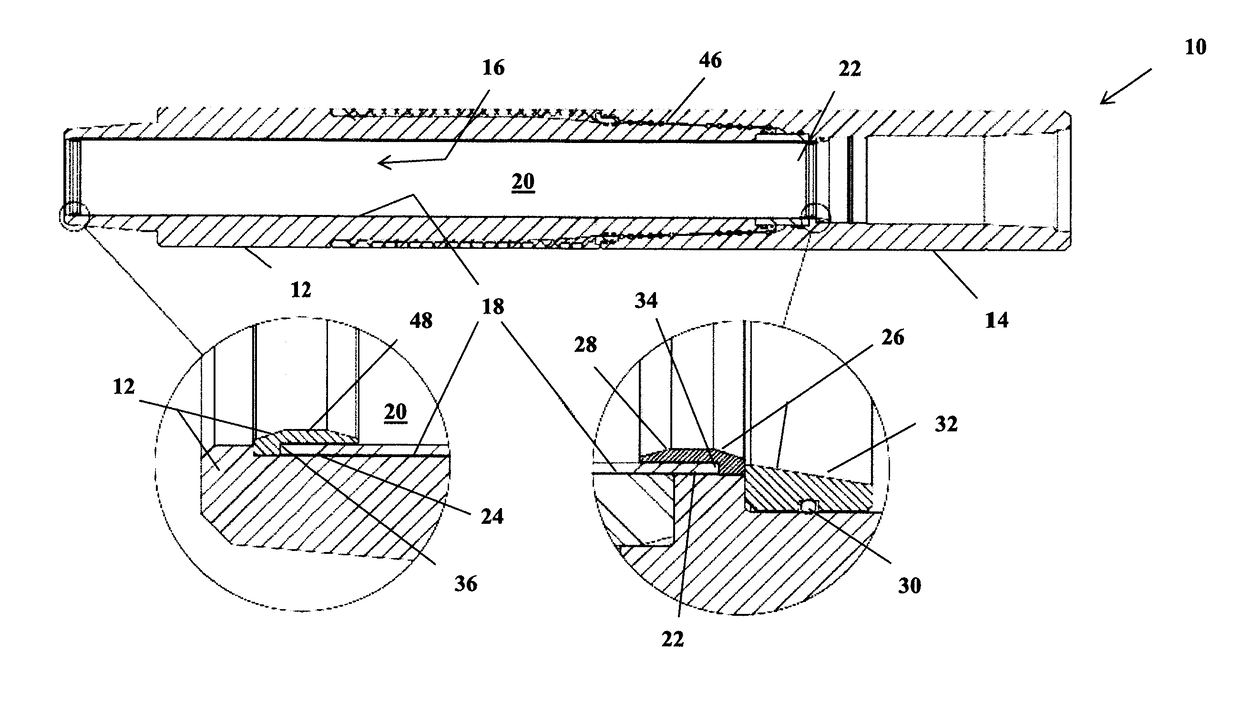
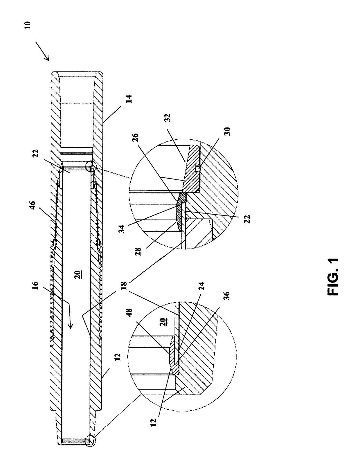
[0055]Throughout the following description specific details are set forth in order to provide a more thorough understanding to persons skilled in the art. However, well known elements may not have been shown or described in detail to avoid unnecessarily obscuring the disclosure. The following description of examples of the technology is not intended to be exhaustive or to limit the invention to the precise forms of any exemplary embodiment. Accordingly, the description and drawings are to be regarded in an illustrative, rather than a restrictive, sense. For example, although the present invention is illustrated as being applied to a gap sub for use in electromagnetic telemetry operations, the present invention may be applied to any appropriate or suitable protective wear and / or electrical isolation member used with pipes or conduits.

[0056]Turning now to FIG. 1, a gap sub 10 is illustrated. The gap sub 10 comprises a male member 12 and a female member 14 separated by a gap member 46,...


PUM

PropertyMeasurementUnit
electrically insulativeaaaaaaaaaa
electrically isolativeaaaaaaaaaa
volumeaaaaaaaaaa

Abstract

A device and method for securing a sleeve (for sacrificial wear and/or electrical isolation) inside a conduit. In one embodiment, the retention device sits adjacent one end of the sleeve and comprises a ring having a protuberance or lip extending parallel to and against the end of the sleeve, thus pressing the end of the sleeve against the inner surface of the conduit. This has the advantage, in situations where fluids are flowing through the conduit, of reducing the risk of fluids moving behind the sleeve and collapsing it inwardly.

Description

FIELD OF THE INVENTION[0001]The present invention relates to protective techniques and methodologies for conduit interiors, and more specifically to the use of sleeves as wear members or electrical insulators.BACKGROUND OF THE INVENTION[0002]It is known in the art of conduit design to employ covers or coatings to protect the inner conduit surfaces from corrosion or undue wear, as abrasive liquid / solid mixtures are often transported in a pipeline or conduit. The covers may be manufactured separately and inserted into the conduit, or they may be in the form of a spray-coating or similar application technique. The cover or sleeve material is commonly in the form of a plastic or metal material, the specific material selected on the basis of the application and the type, volume and velocity of fluid flow through the conduit.[0003]For example, U.S. Pat. No. 8,397,766 to Rosen teaches a pipe welding method wherein adjacent pipe sections are provided with a plastic lining. The plastic linin...

Claims


Application Information

Patent Timeline
Patent Type & Authority Applications(United States)
IPC IPC(8): E21B17/10F16L58/10E21B17/00F16L57/06
CPCF16L57/06E21B47/122E21B17/1007F16L58/1036E21B17/003F16L57/02F16L58/1009F16L55/1657F16L58/182E21B17/042
Inventor STACK, LUKE ANTHONYSWITZER, DAVELOGAN, JUSTIN CHRISTOPHERLOGAN, AARON WILLIAM
Owner EVOLUTION ENG
Why Eureka
Try Eureka