Adhesion of thermal spray using compression technique

a compression technique and thermal spray coating technology, applied in the field of adhesives, can solve the problems of poor bonding, thermal spray coating cracking or peeling, time-consuming process, etc., and achieve the effect of improving the adhesion of thermal spray coating, and improving the texture of substrate surfa

Active Publication Date: 2018-02-15
GM GLOBAL TECH OPERATIONS LLC
View PDF3 Cites 3 Cited by
  • Summary
  • Abstract
  • Description
  • Claims
  • Application Information

AI Technical Summary

Benefits of technology

[0005]The present disclosure provides an improved substrate surface texture, which improves the adhesion of thermal spray c

Problems solved by technology

However, it has been determined that, in fact, typically the most significant factor affecting the ruggedness and durability of a thermal spray coating is the strength of the bond between the thermal spray coating and the surface.
A poor bond may allow the thermal spray coating to crack or peel off, sometimes in relatively large pieces, long before the th

Method used


Image

  • Adhesion of thermal spray using compression technique
  • Adhesion of thermal spray using compression technique
  • Adhesion of thermal spray using compression technique

Examples


Embodiment Construction

[0031]The following description is merely exemplary in nature and is not intended to limit the present disclosure, application, or uses.

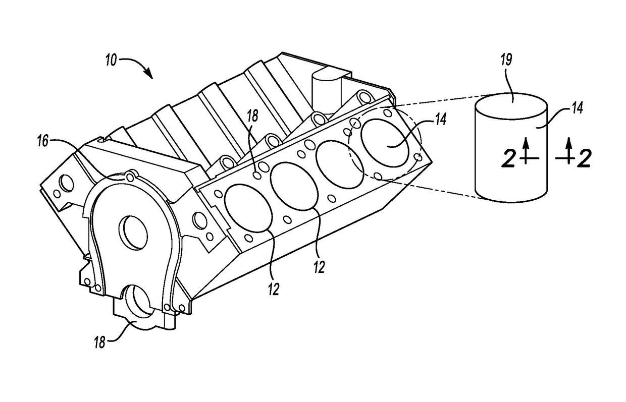
[0032]With reference to FIG. 1, an internal combustion engine block is illustrated and generally designated by the reference number 10. The engine block 10 typically includes a plurality of cylinders 12 having interior cylinder bores 14, numerous flanges 16 and openings 18 for threaded fasteners and other features for receiving and securing components such as cylinder heads, shafts, manifolds and covers (all not illustrated).

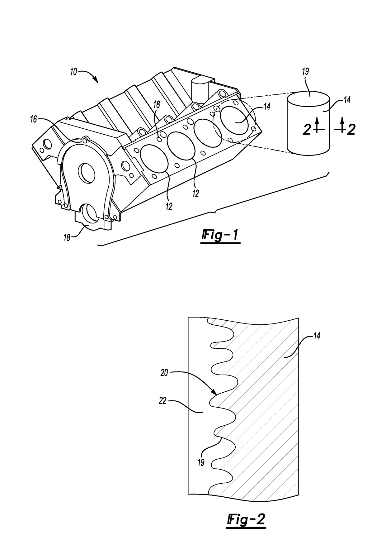
[0033]On the right side of FIG. 1 is an enlarged representation of the cylinder bore 14. The cylinder bore 14 may be a surface of a substrate such as an aluminum engine block 10 or a surface of an iron sleeve that has been installed in the engine block 10. Thus, the cylinder bore 14 has an inner surface wall 19. In either case, the surface finish of the inner surface 19 of the cylinder bore 14 may be a machined profile which is ...


PUM

PropertyMeasurementUnit
Lengthaaaaaaaaaa
Fractionaaaaaaaaaa
Pressureaaaaaaaaaa

Abstract

An improved surface activation technique improves the adhesion of thermal spray coatings, which is useful for engine cylinder bores. The new method includes compressing the cylinder bore surface to create a surface profile on the surface, such as through rolling a roller along the surface. An engine block is also provided, which includes a plurality of cylinder bores, each cylinder bore having an inner surface, and each inner surface having a surface profile that includes a helical groove and other surface profiles formed in the inner surface. A thermal spray coating is formed on the inner surface of each cylinder bore, the thermal spray coating being adhered to the surface profile of the inner surface. A roller assembly for activating the surface is also provided.

Description

FIELD[0001]The present disclosure relates to improving the adhesion of thermal spray coatings to surfaces and more particularly to surface activation that provides improved adhesion of thermal spray coatings to such surfaces.INTRODUCTION[0002]Thermal spraying is a coating process which applies material heated and typically melted by combustion or an electrical plasma or arc to a substrate. The process is capable of rapidly applying a relatively thick coating over a large area relative to other coating processes such as electroplating, sputtering and physical and vapor deposition.[0003]The ruggedness and durability of the thermal spray coating would seem to be almost exclusively a feature of the material of the coating and to a lesser extent the quality of application. However, it has been determined that, in fact, typically the most significant factor affecting the ruggedness and durability of a thermal spray coating is the strength of the bond between the thermal spray coating and ...

Claims


Application Information

Patent Timeline
IPC IPC(8): F02F1/00F02F7/00F02F1/18C23C4/12
CPCF02F1/004C23C4/12F02F2200/00F02F1/18F02F7/0012C23C4/02B24B5/06
Inventor YANG, JIANGHUAIWANG, QIGUIKRAMER, MARTIN SGERARD, DALE A
Owner GM GLOBAL TECH OPERATIONS LLC
Why Eureka
Try Eureka